

Safety of 5G Network Physical Infrastructures 179
dynamic analysis is complex and time‐consuming, a simplified analysis method was
developed by using an equivalent quasi‐static analysis through “patch” loading techniques (see Annex B of EN 1993‐3‐1).
8.3.3 Structural Analysis
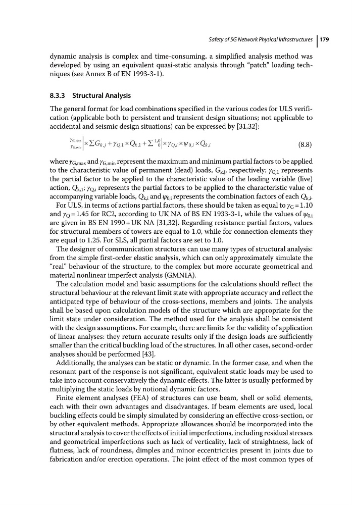
The general format for load combinations specified in the various codes for ULS verification (applicable both to persistent and transient design situations; not applicable to
accidental and seismic design situations) can be expressed by [31,32]:
G min
G max
G
Q
Q
k j
Q
k
Q i
i
ki
,
,
,
,
,
,
,
,
,
1
1
0
1 0
0
(8.8)
where γ G,max and γ G,min represent the maximum and minimum partial factors to be applied
to the characteristic value of permanent (dead) loads, G k,j , respectively; γ Q,1 represents
the partial factor to be applied to the characteristic value of the leading variable (live)
action, Q k,1 ; γ Q,i represents the partial factors to be applied to the characteristic value of
accompanying variable loads, Q k,i and ψ 0,i represents the combination factors of each Q k,i .
For ULS, in terms of actions partial factors, these should be taken as equal to γ G = 1.10
and γ Q = 1.45 for RC2, according to UK NA of BS EN 1933‐3‐1, while the values of ψ 0,i
are given in BS EN 1990 + UK NA [31,32]. Regarding resistance partial factors, values
for structural members of towers are equal to 1.0, while for connection elements they
are equal to 1.25. For SLS, all partial factors are set to 1.0.
The designer of communication structures can use many types of structural analysis:
from the simple first‐order elastic analysis, which can only approximately simulate the
“real” behaviour of the structure, to the complex but more accurate geometrical and
material nonlinear imperfect analysis (GMNIA).
The calculation model and basic assumptions for the calculations should reflect the
structural behaviour at the relevant limit state with appropriate accuracy and reflect the
anticipated type of behaviour of the cross‐sections, members and joints. The analysis
shall be based upon calculation models of the structure which are appropriate for the
limit state under consideration. The method used for the analysis shall be consistent
with the design assumptions. For example, there are limits for the validity of application
of linear analyses: they return accurate results only if the design loads are sufficiently
smaller than the critical buckling load of the structures. In all other cases, second‐order
analyses should be performed [43].
Additionally, the analyses can be static or dynamic. In the former case, and when the
resonant part of the response is not significant, equivalent static loads may be used to
take into account conservatively the dynamic effects. The latter is usually performed by
multiplying the static loads by notional dynamic factors.
Finite element analyses (FEA) of structures can use beam, shell or solid elements,
each with their own advantages and disadvantages. If beam elements are used, local
buckling effects could be simply simulated by considering an effective cross‐section, or
by other equivalent methods. Appropriate allowances should be incorporated into the
structural analysis to cover the effects of initial imperfections, including residual stresses
and geometrical imperfections such as lack of verticality, lack of straightness, lack of
flatness, lack of roundness, dimples and minor eccentricities present in joints due to
fabrication and/or erection operations. The joint effect of the most common types of
dynamic analysis is complex and time‐consuming, a simplified analysis method was
developed by using an equivalent quasi‐static analysis through “patch” loading techniques (see Annex B of EN 1993‐3‐1).
8.3.3 Structural Analysis
The general format for load combinations specified in the various codes for ULS verification (applicable both to persistent and transient design situations; not applicable to
accidental and seismic design situations) can be expressed by [31,32]:
G min
G max
G
Q
Q
k j
Q
k
Q i
i
ki
,
,
,
,
,
,
,
,
,
1
1
0
1 0
0
(8.8)
where γ G,max and γ G,min represent the maximum and minimum partial factors to be applied
to the characteristic value of permanent (dead) loads, G k,j , respectively; γ Q,1 represents
the partial factor to be applied to the characteristic value of the leading variable (live)
action, Q k,1 ; γ Q,i represents the partial factors to be applied to the characteristic value of
accompanying variable loads, Q k,i and ψ 0,i represents the combination factors of each Q k,i .
For ULS, in terms of actions partial factors, these should be taken as equal to γ G = 1.10
and γ Q = 1.45 for RC2, according to UK NA of BS EN 1933‐3‐1, while the values of ψ 0,i
are given in BS EN 1990 + UK NA [31,32]. Regarding resistance partial factors, values
for structural members of towers are equal to 1.0, while for connection elements they
are equal to 1.25. For SLS, all partial factors are set to 1.0.
The designer of communication structures can use many types of structural analysis:
from the simple first‐order elastic analysis, which can only approximately simulate the
“real” behaviour of the structure, to the complex but more accurate geometrical and
material nonlinear imperfect analysis (GMNIA).
The calculation model and basic assumptions for the calculations should reflect the
structural behaviour at the relevant limit state with appropriate accuracy and reflect the
anticipated type of behaviour of the cross‐sections, members and joints. The analysis
shall be based upon calculation models of the structure which are appropriate for the
limit state under consideration. The method used for the analysis shall be consistent
with the design assumptions. For example, there are limits for the validity of application
of linear analyses: they return accurate results only if the design loads are sufficiently
smaller than the critical buckling load of the structures. In all other cases, second‐order
analyses should be performed [43].
Additionally, the analyses can be static or dynamic. In the former case, and when the
resonant part of the response is not significant, equivalent static loads may be used to
take into account conservatively the dynamic effects. The latter is usually performed by
multiplying the static loads by notional dynamic factors.
Finite element analyses (FEA) of structures can use beam, shell or solid elements,
each with their own advantages and disadvantages. If beam elements are used, local
buckling effects could be simply simulated by considering an effective cross‐section, or
by other equivalent methods. Appropriate allowances should be incorporated into the
structural analysis to cover the effects of initial imperfections, including residual stresses
and geometrical imperfections such as lack of verticality, lack of straightness, lack of
flatness, lack of roundness, dimples and minor eccentricities present in joints due to
fabrication and/or erection operations. The joint effect of the most common types of