

Physical Layer Security 125
where (x W (i)) k is the k‐th data bit of the watermark signal, (c W (i)) j represents the j‐th
chip of the orthogonal pseudo‐noise (PN) sequence, g(i) is the pulse waveform, T c is the
chip length, and T N T
b
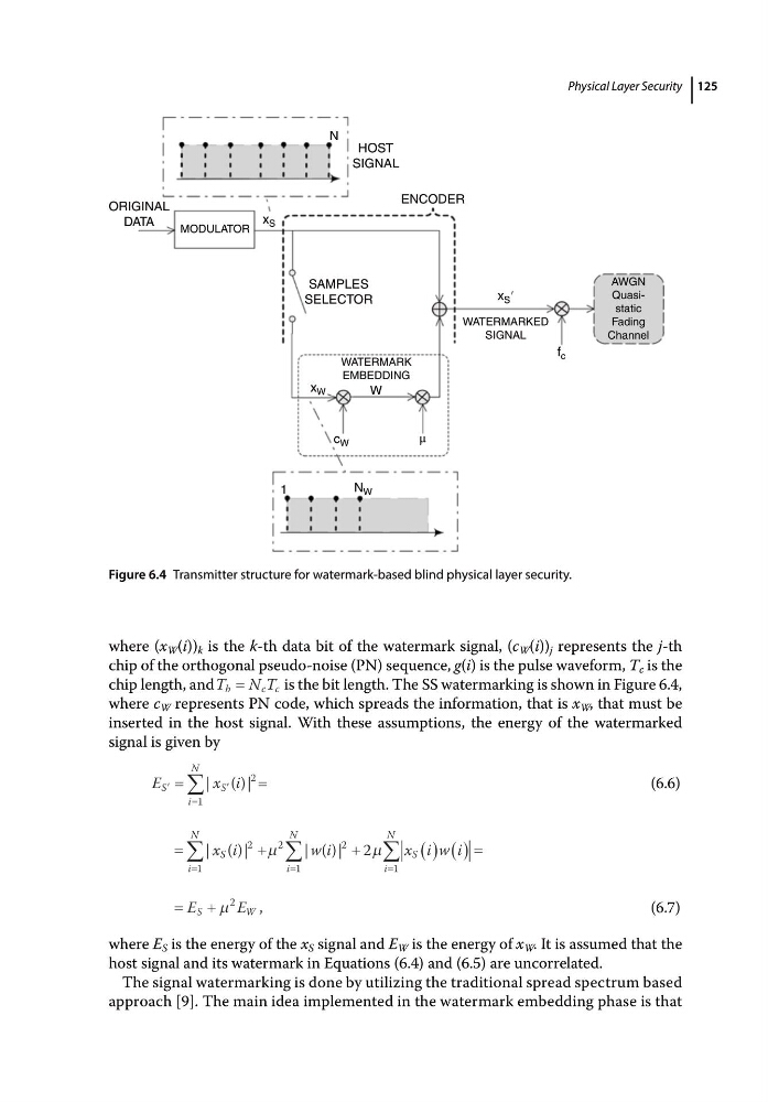
c c is the bit length. The SS watermarking is shown in Figure 6.4,
where c W represents PN code, which spreads the information, that is x W , that must be
inserted in the host signal. With these assumptions, the energy of the watermarked
signal is given by
E
x i
S
i
N
S
1
2
| ( )|
(6.6)
i
N
S
i
N
i
N
S
x i
w i
x i w i
1
2
2
1
2
1
2
| ( )|
| ( )|
E
E
S
W
2
,
(6.7)
where E S is the energy of the x S signal and E W is the energy of x W . It is assumed that the
host signal and its watermark in Equations (6.4) and (6.5) are uncorrelated.
The signal watermarking is done by utilizing the traditional spread spectrum based
approach [9]. The main idea implemented in the watermark embedding phase is that
SAMPLES
SELECTOR
MODULATOR
ORIGINAL
DATA
WATERMARK
EMBEDDING
WATERMARKED
SIGNAL
f c
x S ′
W
x W
x S
c W
μ
N W
1
AWGN
Quasistatic
Fading
Channel
ENCODER
HOST
SIGNAL
N
Figure 6.4 Transmitter structure for watermark‐based blind physical layer security.
where (x W (i)) k is the k‐th data bit of the watermark signal, (c W (i)) j represents the j‐th
chip of the orthogonal pseudo‐noise (PN) sequence, g(i) is the pulse waveform, T c is the
chip length, and T N T
b
c c is the bit length. The SS watermarking is shown in Figure 6.4,
where c W represents PN code, which spreads the information, that is x W , that must be
inserted in the host signal. With these assumptions, the energy of the watermarked
signal is given by
E
x i
S
i
N
S
1
2
| ( )|
(6.6)
i
N
S
i
N
i
N
S
x i
w i
x i w i
1
2
2
1
2
1
2
| ( )|
| ( )|
E
E
S
W
2
,
(6.7)
where E S is the energy of the x S signal and E W is the energy of x W . It is assumed that the
host signal and its watermark in Equations (6.4) and (6.5) are uncorrelated.
The signal watermarking is done by utilizing the traditional spread spectrum based
approach [9]. The main idea implemented in the watermark embedding phase is that
SAMPLES
SELECTOR
MODULATOR
ORIGINAL
DATA
WATERMARK
EMBEDDING
WATERMARKED
SIGNAL
f c
x S ′
W
x W
x S
c W
μ
N W
1
AWGN
Quasistatic
Fading
Channel
ENCODER
HOST
SIGNAL
N
Figure 6.4 Transmitter structure for watermark‐based blind physical layer security.