

134 5 SDN and NFV in 5G
State
Match
Action
NEW
WAIT
EST
NF
documentation
NF
configuration
NF
testing/analysis
Expert
knowledge
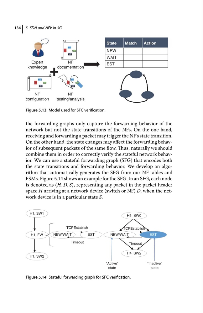
Figure 5.13 Model used for SFC verification.
the forwarding graphs only capture the forwarding behavior of the
network but not the state transitions of the NFs. On the one hand,
receiving and forwarding a packet may trigger the NF’s state transition.
On the other hand, the state changes may affect the forwarding behavior of subsequent packets of the same flow. Thus, naturally we should
combine them in order to correctly verify the stateful network behavior. We can use a stateful forwarding graph (SFG) that encodes both
the state transitions and forwarding behavior. We develop an algorithm that automatically generates the SFG from our NF tables and
FSMs. Figure 5.14 shows an example for the SFG. In an SFG, each node
is denoted as ⟨H, D, S⟩, representing any packet in the packet header
space H arriving at a network device (switch or NF) D, when the network device is in a particular state S.
H4, SW2
H1, SW1
H1, FW
NEW/WAIT
EST
Timeout
TCPEstablish
“Active”
state
“Inactive”
state
H1, SW2
NEW/WAIT
EST
Timeout
TCPEstablish
H1, SW0
Figure 5.14 Stateful forwarding graph for SFC verification.
State
Match
Action
NEW
WAIT
EST
NF
documentation
NF
configuration
NF
testing/analysis
Expert
knowledge
Figure 5.13 Model used for SFC verification.
the forwarding graphs only capture the forwarding behavior of the
network but not the state transitions of the NFs. On the one hand,
receiving and forwarding a packet may trigger the NF’s state transition.
On the other hand, the state changes may affect the forwarding behavior of subsequent packets of the same flow. Thus, naturally we should
combine them in order to correctly verify the stateful network behavior. We can use a stateful forwarding graph (SFG) that encodes both
the state transitions and forwarding behavior. We develop an algorithm that automatically generates the SFG from our NF tables and
FSMs. Figure 5.14 shows an example for the SFG. In an SFG, each node
is denoted as ⟨H, D, S⟩, representing any packet in the packet header
space H arriving at a network device (switch or NF) D, when the network device is in a particular state S.
H4, SW2
H1, SW1
H1, FW
NEW/WAIT
EST
Timeout
TCPEstablish
“Active”
state
“Inactive”
state
H1, SW2
NEW/WAIT
EST
Timeout
TCPEstablish
H1, SW0
Figure 5.14 Stateful forwarding graph for SFC verification.