

28 Optimization of Welding Parameters for Self-Support …
301
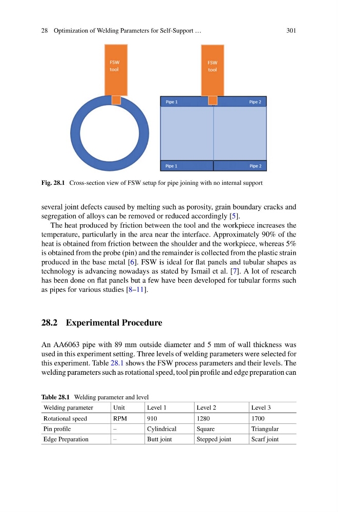
Fig. 28.1 Cross-section view of FSW setup for pipe joining with no internal support
several joint defects caused by melting such as porosity, grain boundary cracks and
segregation of alloys can be removed or reduced accordingly [5].
The heat produced by friction between the tool and the workpiece increases the
temperature, particularly in the area near the interface. Approximately 90% of the
heat is obtained from friction between the shoulder and the workpiece, whereas 5%
is obtained from the probe (pin) and the remainder is collected from the plastic strain
produced in the base metal [6]. FSW is ideal for flat panels and tubular shapes as
technology is advancing nowadays as stated by Ismail et al. [7]. A lot of research
has been done on flat panels but a few have been developed for tubular forms such
as pipes for various studies [8–11].
28.2 Experimental Procedure
An AA6063 pipe with 89 mm outside diameter and 5 mm of wall thickness was
used in this experiment setting. Three levels of welding parameters were selected for
this experiment. Table 28.1 shows the FSW process parameters and their levels. The
welding parameters such as rotational speed, tool pin profile and edge preparation can
Table 28.1 Welding parameter and level
Welding parameter
Unit
Level 1
Level 2
Level 3
Rotational speed
RPM
910
1280
1700
Pin profile
–
Cylindrical
Square
Triangular
Edge Preparation
–
Butt joint
Stepped joint
Scarf joint
301
Fig. 28.1 Cross-section view of FSW setup for pipe joining with no internal support
several joint defects caused by melting such as porosity, grain boundary cracks and
segregation of alloys can be removed or reduced accordingly [5].
The heat produced by friction between the tool and the workpiece increases the
temperature, particularly in the area near the interface. Approximately 90% of the
heat is obtained from friction between the shoulder and the workpiece, whereas 5%
is obtained from the probe (pin) and the remainder is collected from the plastic strain
produced in the base metal [6]. FSW is ideal for flat panels and tubular shapes as
technology is advancing nowadays as stated by Ismail et al. [7]. A lot of research
has been done on flat panels but a few have been developed for tubular forms such
as pipes for various studies [8–11].
28.2 Experimental Procedure
An AA6063 pipe with 89 mm outside diameter and 5 mm of wall thickness was
used in this experiment setting. Three levels of welding parameters were selected for
this experiment. Table 28.1 shows the FSW process parameters and their levels. The
welding parameters such as rotational speed, tool pin profile and edge preparation can
Table 28.1 Welding parameter and level
Welding parameter
Unit
Level 1
Level 2
Level 3
Rotational speed
RPM
910
1280
1700
Pin profile
–
Cylindrical
Square
Triangular
Edge Preparation
–
Butt joint
Stepped joint
Scarf joint