

202
M. R. Zoolfakar and I. I. Chacha
60.
75.
90.
105.
120.
100
110
120
130
140
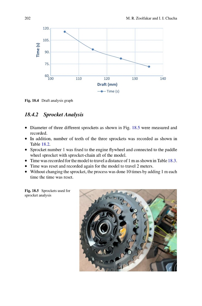
Time (s)
Draft (mm)
Time (s)
Fig. 18.4 Draft analysis graph
18.4.2 Sprocket Analysis
• Diameter of three different sprockets as shown in Fig. 18.5 were measured and
recorded.
• In addition, number of teeth of the three sprockets was recorded as shown in
Table 18.2.
• Sprocket number 1 was fixed to the engine flywheel and connected to the paddle
wheel sprocket with sprocket-chain aft of the model.
• Time was recorded for the model to travel a distance of 1 m as shown in Table 18.3.
• Time was reset and recorded again for the model to travel 2 meters.
• Without changing the sprocket, the process was done 10 times by adding 1 m each
time the time was reset.
Fig. 18.5 Sprockets used for
sprocket analysis
M. R. Zoolfakar and I. I. Chacha
60.
75.
90.
105.
120.
100
110
120
130
140
Time (s)
Draft (mm)
Time (s)
Fig. 18.4 Draft analysis graph
18.4.2 Sprocket Analysis
• Diameter of three different sprockets as shown in Fig. 18.5 were measured and
recorded.
• In addition, number of teeth of the three sprockets was recorded as shown in
Table 18.2.
• Sprocket number 1 was fixed to the engine flywheel and connected to the paddle
wheel sprocket with sprocket-chain aft of the model.
• Time was recorded for the model to travel a distance of 1 m as shown in Table 18.3.
• Time was reset and recorded again for the model to travel 2 meters.
• Without changing the sprocket, the process was done 10 times by adding 1 m each
time the time was reset.
Fig. 18.5 Sprockets used for
sprocket analysis