

200
M. R. Zoolfakar and I. I. Chacha
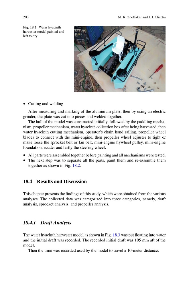
Fig. 18.2 Water hyacinth
harvester model painted and
left to dry
• Cutting and welding
After measuring and marking of the aluminium plate, then by using an electric
grinder, the plate was cut into pieces and welded together.
The hull of the model was constructed initially, followed by the paddling mechanism, propeller mechanism, water hyacinth collection box after being harvested, then
water hyacinth cutting mechanism, operator’s chair, hand railing, propeller wheel
blades to connect with the mini-engine, then propeller wheel adjuster to tight or
make loose the sprocket belt or fan belt, mini-engine flywheel pulley, mini-engine
foundation, rudder and lastly the steering wheel.
• All parts were assembled together before painting and all mechanisms were tested.
• The next step was to separate all the parts, paint them and re-assemble them
together as shown in Fig. 18.2.
18.4 Results and Discussion
This chapter presents the findings of this study, which were obtained from the various
analyses. The collected data was categorized into three categories, namely, draft
analysis, sprocket analysis, and propeller analysis.
18.4.1 Draft Analysis
The water hyacinth harvester model as shown in Fig. 18.3 was put floating into water
and the initial draft was recorded. The recorded initial draft was 105 mm aft of the
model.
Then the time was recorded used by the model to travel a 10-meter distance.
M. R. Zoolfakar and I. I. Chacha
Fig. 18.2 Water hyacinth
harvester model painted and
left to dry
• Cutting and welding
After measuring and marking of the aluminium plate, then by using an electric
grinder, the plate was cut into pieces and welded together.
The hull of the model was constructed initially, followed by the paddling mechanism, propeller mechanism, water hyacinth collection box after being harvested, then
water hyacinth cutting mechanism, operator’s chair, hand railing, propeller wheel
blades to connect with the mini-engine, then propeller wheel adjuster to tight or
make loose the sprocket belt or fan belt, mini-engine flywheel pulley, mini-engine
foundation, rudder and lastly the steering wheel.
• All parts were assembled together before painting and all mechanisms were tested.
• The next step was to separate all the parts, paint them and re-assemble them
together as shown in Fig. 18.2.
18.4 Results and Discussion
This chapter presents the findings of this study, which were obtained from the various
analyses. The collected data was categorized into three categories, namely, draft
analysis, sprocket analysis, and propeller analysis.
18.4.1 Draft Analysis
The water hyacinth harvester model as shown in Fig. 18.3 was put floating into water
and the initial draft was recorded. The recorded initial draft was 105 mm aft of the
model.
Then the time was recorded used by the model to travel a 10-meter distance.