

16 Mitigating Engine Exhaust Emission …
169
16.2.2 Schematic Design
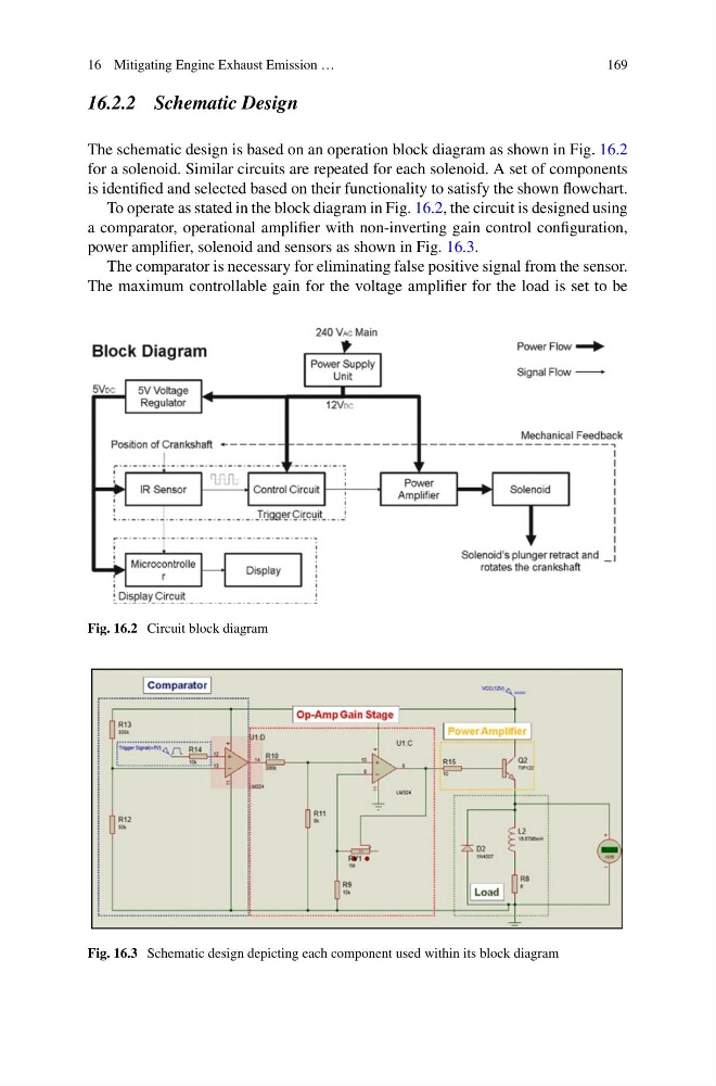
The schematic design is based on an operation block diagram as shown in Fig. 16.2
for a solenoid. Similar circuits are repeated for each solenoid. A set of components
is identified and selected based on their functionality to satisfy the shown flowchart.
To operate as stated in the block diagram in Fig. 16.2, the circuit is designed using
a comparator, operational amplifier with non-inverting gain control configuration,
power amplifier, solenoid and sensors as shown in Fig. 16.3.
The comparator is necessary for eliminating false positive signal from the sensor.
The maximum controllable gain for the voltage amplifier for the load is set to be
Fig. 16.2 Circuit block diagram
Fig. 16.3 Schematic design depicting each component used within its block diagram
169
16.2.2 Schematic Design
The schematic design is based on an operation block diagram as shown in Fig. 16.2
for a solenoid. Similar circuits are repeated for each solenoid. A set of components
is identified and selected based on their functionality to satisfy the shown flowchart.
To operate as stated in the block diagram in Fig. 16.2, the circuit is designed using
a comparator, operational amplifier with non-inverting gain control configuration,
power amplifier, solenoid and sensors as shown in Fig. 16.3.
The comparator is necessary for eliminating false positive signal from the sensor.
The maximum controllable gain for the voltage amplifier for the load is set to be
Fig. 16.2 Circuit block diagram
Fig. 16.3 Schematic design depicting each component used within its block diagram