

CFD Analysis on Extrusion of Slurry in Direct Ink Writing
71
3.3 Inlet and Outlet Pressures
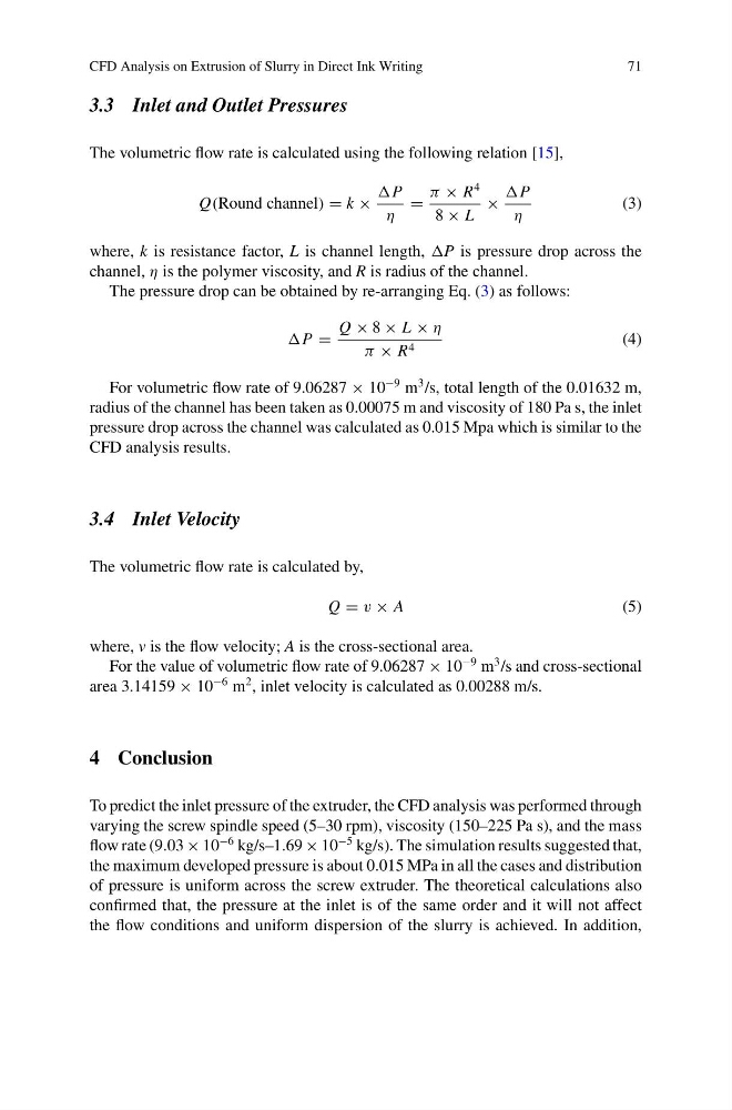
The volumetric flow rate is calculated using the following relation [15],
Q(Round channel) = k ×
P
η
=
π × R
4
8 × L
×
P
η
(3)
where, k is resistance factor, L is channel length, P is pressure drop across the
channel, η is the polymer viscosity, and R is radius of the channel.
The pressure drop can be obtained by re-arranging Eq. (3) as follows:
P =
Q × 8 × L × η
π × R 4
(4)
For volumetric flow rate of 9.06287 × 10
−9 m
3 /s, total length of the 0.01632 m,
radius of the channel has been taken as 0.00075 m and viscosity of 180 Pa s, the inlet
pressure drop across the channel was calculated as 0.015 Mpa which is similar to the
CFD analysis results.
3.4 Inlet Velocity
The volumetric flow rate is calculated by,
Q = v × A
(5)
where, v is the flow velocity; A is the cross-sectional area.
For the value of volumetric flow rate of 9.06287 × 10
−9 m
3 /s and cross-sectional
area 3.14159 × 10
−6 m
2 , inlet velocity is calculated as 0.00288 m/s.
4 Conclusion
To predict the inlet pressure of the extruder, the CFD analysis was performed through
varying the screw spindle speed (5–30 rpm), viscosity (150–225 Pa s), and the mass
flow rate (9.03 × 10
−6 kg/s–1.69 × 10
−5 kg/s). The simulation results suggested that,
the maximum developed pressure is about 0.015 MPa in all the cases and distribution
of pressure is uniform across the screw extruder. The theoretical calculations also
confirmed that, the pressure at the inlet is of the same order and it will not affect
the flow conditions and uniform dispersion of the slurry is achieved. In addition,
71
3.3 Inlet and Outlet Pressures
The volumetric flow rate is calculated using the following relation [15],
Q(Round channel) = k ×
P
η
=
π × R
4
8 × L
×
P
η
(3)
where, k is resistance factor, L is channel length, P is pressure drop across the
channel, η is the polymer viscosity, and R is radius of the channel.
The pressure drop can be obtained by re-arranging Eq. (3) as follows:
P =
Q × 8 × L × η
π × R 4
(4)
For volumetric flow rate of 9.06287 × 10
−9 m
3 /s, total length of the 0.01632 m,
radius of the channel has been taken as 0.00075 m and viscosity of 180 Pa s, the inlet
pressure drop across the channel was calculated as 0.015 Mpa which is similar to the
CFD analysis results.
3.4 Inlet Velocity
The volumetric flow rate is calculated by,
Q = v × A
(5)
where, v is the flow velocity; A is the cross-sectional area.
For the value of volumetric flow rate of 9.06287 × 10
−9 m
3 /s and cross-sectional
area 3.14159 × 10
−6 m
2 , inlet velocity is calculated as 0.00288 m/s.
4 Conclusion
To predict the inlet pressure of the extruder, the CFD analysis was performed through
varying the screw spindle speed (5–30 rpm), viscosity (150–225 Pa s), and the mass
flow rate (9.03 × 10
−6 kg/s–1.69 × 10
−5 kg/s). The simulation results suggested that,
the maximum developed pressure is about 0.015 MPa in all the cases and distribution
of pressure is uniform across the screw extruder. The theoretical calculations also
confirmed that, the pressure at the inlet is of the same order and it will not affect
the flow conditions and uniform dispersion of the slurry is achieved. In addition,