

356
G. Vishnu Teja and M. Meikandan
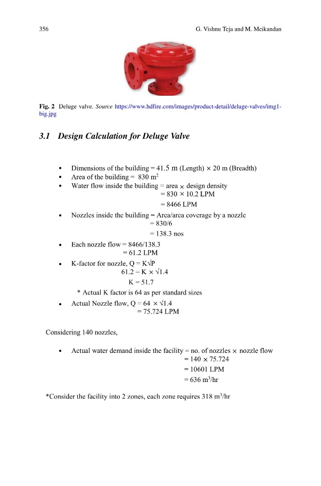
Fig. 2 Deluge valve. Source https://www.hdfire.com/images/product-detail/deluge-valves/img1big.jpg
3.1 Design Calculation for Deluge Valve
Dimensions of the building = 41.5 m (Length) 20 m (Breadth)
Area of the building = 830 m
2
Water flow inside the building = area design density
= 830 10.2 LPM
= 8466 LPM
Nozzles inside the building = Area/area coverage by a nozzle
= 830/6
= 138.3 nos
Each nozzle flow = 8466/138.3
= 61.2 LPM
K-factor for nozzle, Q = K√P
61.2 = K √1.4
K = 51.7
* Actual K factor is 64 as per standard sizes
Actual Nozzle flow, Q = 64 √1.4
= 75.724 LPM
Considering 140 nozzles,
Actual water demand inside the facility = no. of nozzles nozzle flow
= 140 75.724
= 10601 LPM
= 636 m
3
/hr
*Consider the facility into 2 zones, each zone requires 318 m
3 /hr
G. Vishnu Teja and M. Meikandan
Fig. 2 Deluge valve. Source https://www.hdfire.com/images/product-detail/deluge-valves/img1big.jpg
3.1 Design Calculation for Deluge Valve
Dimensions of the building = 41.5 m (Length) 20 m (Breadth)
Area of the building = 830 m
2
Water flow inside the building = area design density
= 830 10.2 LPM
= 8466 LPM
Nozzles inside the building = Area/area coverage by a nozzle
= 830/6
= 138.3 nos
Each nozzle flow = 8466/138.3
= 61.2 LPM
K-factor for nozzle, Q = K√P
61.2 = K √1.4
K = 51.7
* Actual K factor is 64 as per standard sizes
Actual Nozzle flow, Q = 64 √1.4
= 75.724 LPM
Considering 140 nozzles,
Actual water demand inside the facility = no. of nozzles nozzle flow
= 140 75.724
= 10601 LPM
= 636 m
3
/hr
*Consider the facility into 2 zones, each zone requires 318 m
3 /hr