

Quieter Cabin Through Reduction in Uncontrolled …
305
Fig. 1 Air leakage testing methodology
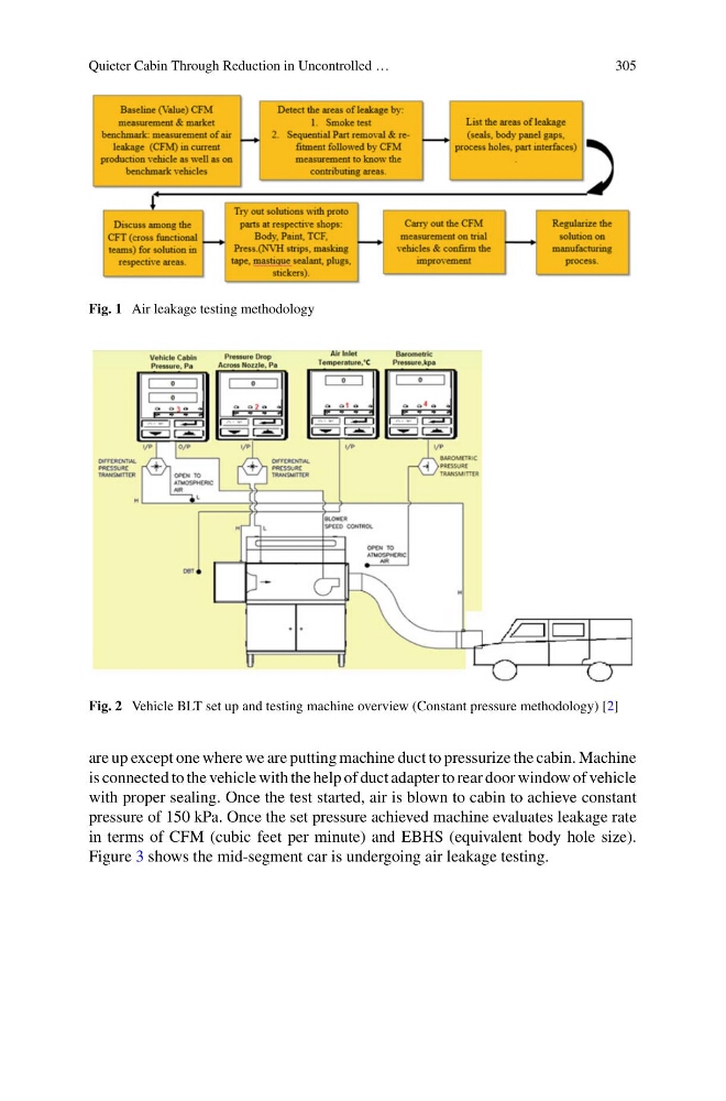
Fig. 2 Vehicle BLT set up and testing machine overview (Constant pressure methodology) [2]
are up except one where we are putting machine duct to pressurize the cabin. Machine
is connected to the vehicle with the help of duct adapter to rear door window of vehicle
with proper sealing. Once the test started, air is blown to cabin to achieve constant
pressure of 150 kPa. Once the set pressure achieved machine evaluates leakage rate
in terms of CFM (cubic feet per minute) and EBHS (equivalent body hole size).
Figure 3 shows the mid-segment car is undergoing air leakage testing.
305
Fig. 1 Air leakage testing methodology
Fig. 2 Vehicle BLT set up and testing machine overview (Constant pressure methodology) [2]
are up except one where we are putting machine duct to pressurize the cabin. Machine
is connected to the vehicle with the help of duct adapter to rear door window of vehicle
with proper sealing. Once the test started, air is blown to cabin to achieve constant
pressure of 150 kPa. Once the set pressure achieved machine evaluates leakage rate
in terms of CFM (cubic feet per minute) and EBHS (equivalent body hole size).
Figure 3 shows the mid-segment car is undergoing air leakage testing.