

298
K. Giridharan et al.
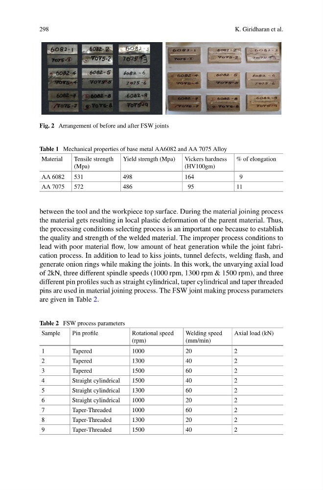
Fig. 2 Arrangement of before and after FSW joints
Table 1 Mechanical properties of base metal AA6082 and AA 7075 Alloy
Material
Tensile strength
(Mpa)
Yield strength (Mpa)
Vickers hardness
(HV100gm)
% of elongation
AA 6082
531
498
164
9
AA 7075
572
486
95
11
between the tool and the workpiece top surface. During the material joining process
the material gets resulting in local plastic deformation of the parent material. Thus,
the processing conditions selecting process is an important one because to establish
the quality and strength of the welded material. The improper process conditions to
lead with poor material flow, low amount of heat generation while the joint fabrication process. In addition to lead to kiss joints, tunnel defects, welding flash, and
generate onion rings while making the joints. In this work, the unvarying axial load
of 2kN, three different spindle speeds (1000 rpm, 1300 rpm & 1500 rpm), and three
different pin profiles such as straight cylindrical, taper cylindrical and taper threaded
pins are used in material joining process. The FSW joint making process parameters
are given in Table 2.
Table 2 FSW process parameters
Sample
Pin profile
Rotational speed
(rpm)
Welding speed
(mm/min)
Axial load (kN)
1
Tapered
1000
20
2
2
Tapered
1300
40
2
3
Tapered
1500
60
2
4
Straight cylindrical
1500
40
2
5
Straight cylindrical
1300
60
2
6
Straight cylindrical
1000
20
2
7
Taper-Threaded
1000
60
2
8
Taper-Threaded
1300
20
2
9
Taper-Threaded
1500
40
2
K. Giridharan et al.
Fig. 2 Arrangement of before and after FSW joints
Table 1 Mechanical properties of base metal AA6082 and AA 7075 Alloy
Material
Tensile strength
(Mpa)
Yield strength (Mpa)
Vickers hardness
(HV100gm)
% of elongation
AA 6082
531
498
164
9
AA 7075
572
486
95
11
between the tool and the workpiece top surface. During the material joining process
the material gets resulting in local plastic deformation of the parent material. Thus,
the processing conditions selecting process is an important one because to establish
the quality and strength of the welded material. The improper process conditions to
lead with poor material flow, low amount of heat generation while the joint fabrication process. In addition to lead to kiss joints, tunnel defects, welding flash, and
generate onion rings while making the joints. In this work, the unvarying axial load
of 2kN, three different spindle speeds (1000 rpm, 1300 rpm & 1500 rpm), and three
different pin profiles such as straight cylindrical, taper cylindrical and taper threaded
pins are used in material joining process. The FSW joint making process parameters
are given in Table 2.
Table 2 FSW process parameters
Sample
Pin profile
Rotational speed
(rpm)
Welding speed
(mm/min)
Axial load (kN)
1
Tapered
1000
20
2
2
Tapered
1300
40
2
3
Tapered
1500
60
2
4
Straight cylindrical
1500
40
2
5
Straight cylindrical
1300
60
2
6
Straight cylindrical
1000
20
2
7
Taper-Threaded
1000
60
2
8
Taper-Threaded
1300
20
2
9
Taper-Threaded
1500
40
2