

210
S. Gajjar et al.
1 Introduction
Single point incremental forming (SPIF) process is a dieless advanced sheet metal
forming technique in which the sheet is deformed to a final shape by deforming series
of intermediate shapes. SP ˙ IF is especially suitable for small batch production. SPIF
process has various benefits over conventional sheet forming processes such as relatively high formability, production of parts directly from the computer-aided design
(CAD) file, easy and quick design changes, small forming forces, etc. However, low
geometric accuracy is the main disadvantage that restricts the application of SPIF
process in the industry.
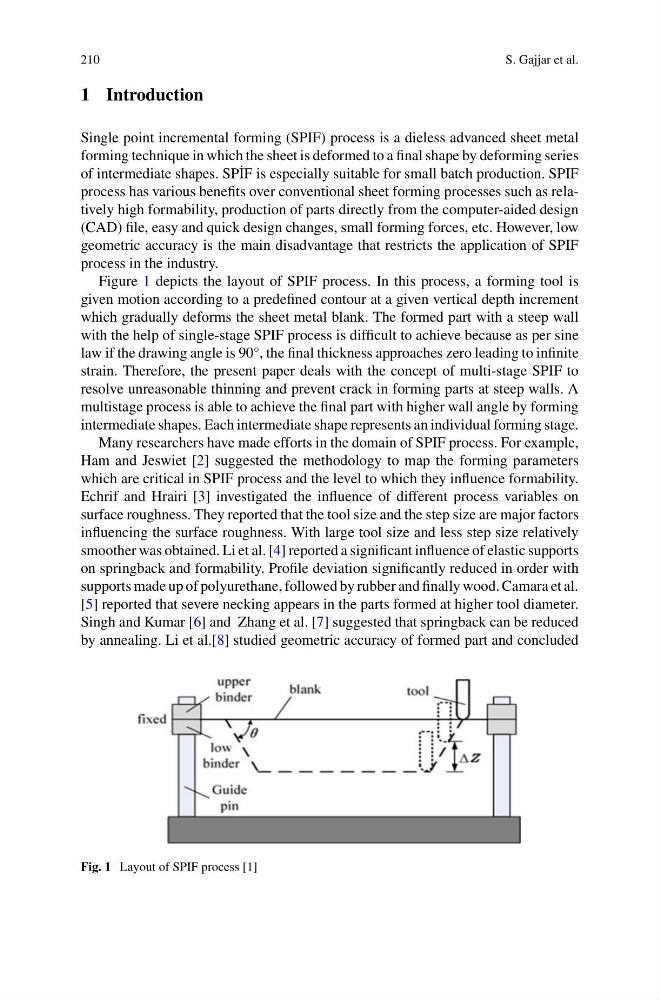
Figure 1 depicts the layout of SPIF process. In this process, a forming tool is
given motion according to a predefined contour at a given vertical depth increment
which gradually deforms the sheet metal blank. The formed part with a steep wall
with the help of single-stage SPIF process is difficult to achieve because as per sine
law if the drawing angle is 90°, the final thickness approaches zero leading to infinite
strain. Therefore, the present paper deals with the concept of multi-stage SPIF to
resolve unreasonable thinning and prevent crack in forming parts at steep walls. A
multistage process is able to achieve the final part with higher wall angle by forming
intermediate shapes. Each intermediate shape represents an individual forming stage.
Many researchers have made efforts in the domain of SPIF process. For example,
Ham and Jeswiet [2] suggested the methodology to map the forming parameters
which are critical in SPIF process and the level to which they influence formability.
Echrif and Hrairi [3] investigated the influence of different process variables on
surface roughness. They reported that the tool size and the step size are major factors
influencing the surface roughness. With large tool size and less step size relatively
smoother was obtained. Li et al. [4] reported a significant influence of elastic supports
on springback and formability. Profile deviation significantly reduced in order with
supports made up of polyurethane, followed by rubber and finally wood. Camara et al.
[5] reported that severe necking appears in the parts formed at higher tool diameter.
Singh and Kumar [6] and Zhang et al. [7] suggested that springback can be reduced
by annealing. Li et al.[8] studied geometric accuracy of formed part and concluded
Fig. 1 Layout of SPIF process [1]
S. Gajjar et al.
1 Introduction
Single point incremental forming (SPIF) process is a dieless advanced sheet metal
forming technique in which the sheet is deformed to a final shape by deforming series
of intermediate shapes. SP ˙ IF is especially suitable for small batch production. SPIF
process has various benefits over conventional sheet forming processes such as relatively high formability, production of parts directly from the computer-aided design
(CAD) file, easy and quick design changes, small forming forces, etc. However, low
geometric accuracy is the main disadvantage that restricts the application of SPIF
process in the industry.
Figure 1 depicts the layout of SPIF process. In this process, a forming tool is
given motion according to a predefined contour at a given vertical depth increment
which gradually deforms the sheet metal blank. The formed part with a steep wall
with the help of single-stage SPIF process is difficult to achieve because as per sine
law if the drawing angle is 90°, the final thickness approaches zero leading to infinite
strain. Therefore, the present paper deals with the concept of multi-stage SPIF to
resolve unreasonable thinning and prevent crack in forming parts at steep walls. A
multistage process is able to achieve the final part with higher wall angle by forming
intermediate shapes. Each intermediate shape represents an individual forming stage.
Many researchers have made efforts in the domain of SPIF process. For example,
Ham and Jeswiet [2] suggested the methodology to map the forming parameters
which are critical in SPIF process and the level to which they influence formability.
Echrif and Hrairi [3] investigated the influence of different process variables on
surface roughness. They reported that the tool size and the step size are major factors
influencing the surface roughness. With large tool size and less step size relatively
smoother was obtained. Li et al. [4] reported a significant influence of elastic supports
on springback and formability. Profile deviation significantly reduced in order with
supports made up of polyurethane, followed by rubber and finally wood. Camara et al.
[5] reported that severe necking appears in the parts formed at higher tool diameter.
Singh and Kumar [6] and Zhang et al. [7] suggested that springback can be reduced
by annealing. Li et al.[8] studied geometric accuracy of formed part and concluded
Fig. 1 Layout of SPIF process [1]