

176
K. S. Vepa et al.
3.3 Forward Phase
In the case of forward motion, quadcopter will move against the wind. Such a scenario
is simulated by keeping the quadcopter in the same position and wind is blown at
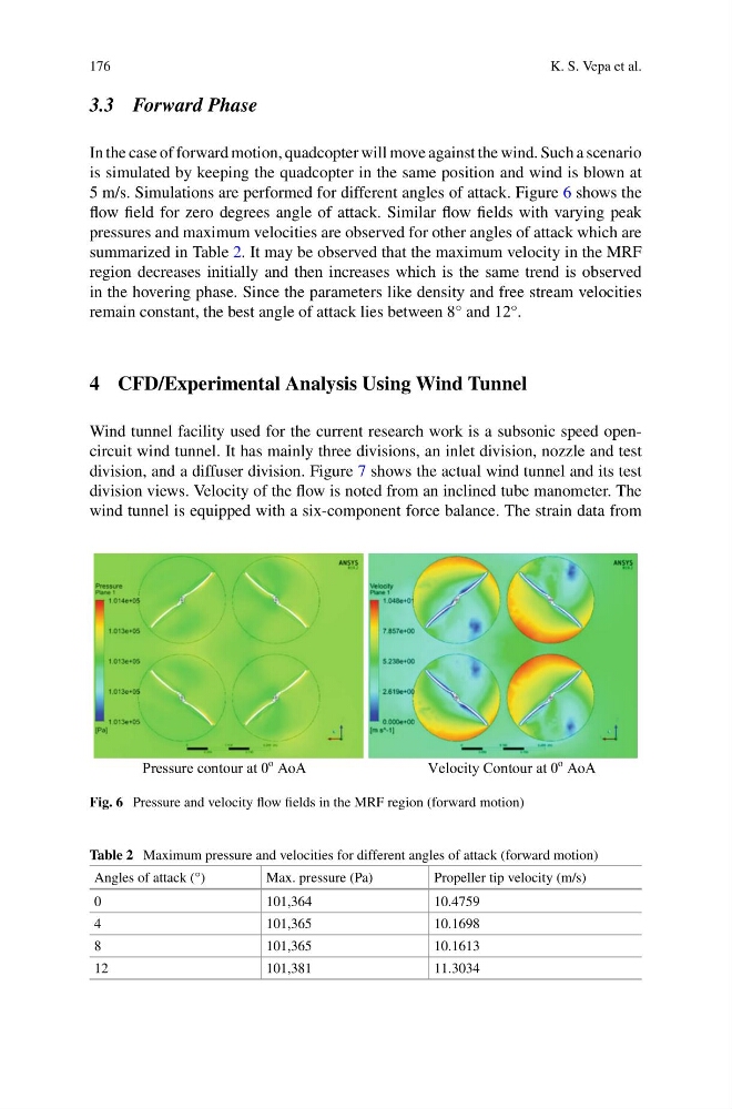
5 m/s. Simulations are performed for different angles of attack. Figure 6 shows the
flow field for zero degrees angle of attack. Similar flow fields with varying peak
pressures and maximum velocities are observed for other angles of attack which are
summarized in Table 2. It may be observed that the maximum velocity in the MRF
region decreases initially and then increases which is the same trend is observed
in the hovering phase. Since the parameters like density and free stream velocities
remain constant, the best angle of attack lies between 8° and 12°.
4 CFD/Experimental Analysis Using Wind Tunnel
Wind tunnel facility used for the current research work is a subsonic speed opencircuit wind tunnel. It has mainly three divisions, an inlet division, nozzle and test
division, and a diffuser division. Figure 7 shows the actual wind tunnel and its test
division views. Velocity of the flow is noted from an inclined tube manometer. The
wind tunnel is equipped with a six-component force balance. The strain data from
Pressure contour at 0
o AoA
Velocity Contour at 0
o AoA
Fig. 6 Pressure and velocity flow fields in the MRF region (forward motion)
Table 2 Maximum pressure and velocities for different angles of attack (forward motion)
Angles of attack (°)
Max. pressure (Pa)
Propeller tip velocity (m/s)
0
101,364
10.4759
4
101,365
10.1698
8
101,365
10.1613
12
101,381
11.3034
K. S. Vepa et al.
3.3 Forward Phase
In the case of forward motion, quadcopter will move against the wind. Such a scenario
is simulated by keeping the quadcopter in the same position and wind is blown at
5 m/s. Simulations are performed for different angles of attack. Figure 6 shows the
flow field for zero degrees angle of attack. Similar flow fields with varying peak
pressures and maximum velocities are observed for other angles of attack which are
summarized in Table 2. It may be observed that the maximum velocity in the MRF
region decreases initially and then increases which is the same trend is observed
in the hovering phase. Since the parameters like density and free stream velocities
remain constant, the best angle of attack lies between 8° and 12°.
4 CFD/Experimental Analysis Using Wind Tunnel
Wind tunnel facility used for the current research work is a subsonic speed opencircuit wind tunnel. It has mainly three divisions, an inlet division, nozzle and test
division, and a diffuser division. Figure 7 shows the actual wind tunnel and its test
division views. Velocity of the flow is noted from an inclined tube manometer. The
wind tunnel is equipped with a six-component force balance. The strain data from
Pressure contour at 0
o AoA
Velocity Contour at 0
o AoA
Fig. 6 Pressure and velocity flow fields in the MRF region (forward motion)
Table 2 Maximum pressure and velocities for different angles of attack (forward motion)
Angles of attack (°)
Max. pressure (Pa)
Propeller tip velocity (m/s)
0
101,364
10.4759
4
101,365
10.1698
8
101,365
10.1613
12
101,381
11.3034