

Thermal Distribution on Gas Turbine Blade Using Thermal Paint
105
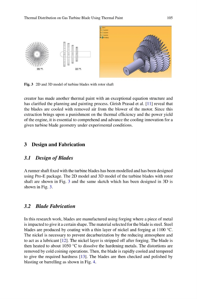
Fig. 3 2D and 3D model of turbine blades with rotor shaft
creator has made another thermal paint with an exceptional equation structure and
has clarified the planning and painting process. Girish Prasad et al. [11] reveal that
the blades are cooled with removed air from the blower of the motor. Since this
extraction brings upon a punishment on the thermal efficiency and the power yield
of the engine, it is essential to comprehend and advance the cooling innovation for a
given turbine blade geometry under experimental conditions.
3 Design and Fabrication
3.1 Design of Blades
A runner shaft fixed with the turbine blades has been modelled and has been designed
using Pro-E package. The 2D model and 3D model of the turbine blades with rotor
shaft are shown in Fig. 3 and the same sketch which has been designed in 3D is
shown in Fig. 3.
3.2 Blade Fabrication
In this research work, blades are manufactured using forging where a piece of metal
is impacted to give it a certain shape. The material selected for the blade is steel. Steel
blades are produced by coating with a thin layer of nickel and forging at 1100 °C.
The nickel is necessary to prevent decarburization by the reducing atmosphere and
to act as a lubricant [12]. The nickel layer is stripped off after forging. The blade is
then heated to about 1050 °C to dissolve the hardening metals. The distortions are
removed by cold coining operations. Then, the blade is rapidly cooled and tempered
to give the required hardness [13]. The blades are then checked and polished by
blasting or barrelling as shown in Fig. 4.
105
Fig. 3 2D and 3D model of turbine blades with rotor shaft
creator has made another thermal paint with an exceptional equation structure and
has clarified the planning and painting process. Girish Prasad et al. [11] reveal that
the blades are cooled with removed air from the blower of the motor. Since this
extraction brings upon a punishment on the thermal efficiency and the power yield
of the engine, it is essential to comprehend and advance the cooling innovation for a
given turbine blade geometry under experimental conditions.
3 Design and Fabrication
3.1 Design of Blades
A runner shaft fixed with the turbine blades has been modelled and has been designed
using Pro-E package. The 2D model and 3D model of the turbine blades with rotor
shaft are shown in Fig. 3 and the same sketch which has been designed in 3D is
shown in Fig. 3.
3.2 Blade Fabrication
In this research work, blades are manufactured using forging where a piece of metal
is impacted to give it a certain shape. The material selected for the blade is steel. Steel
blades are produced by coating with a thin layer of nickel and forging at 1100 °C.
The nickel is necessary to prevent decarburization by the reducing atmosphere and
to act as a lubricant [12]. The nickel layer is stripped off after forging. The blade is
then heated to about 1050 °C to dissolve the hardening metals. The distortions are
removed by cold coining operations. Then, the blade is rapidly cooled and tempered
to give the required hardness [13]. The blades are then checked and polished by
blasting or barrelling as shown in Fig. 4.