

58
4 Layout of a Single Floor
To model the UA-FLP, we use four continuous variables per department, namely
(x i , y i ) to represent the coordinates of the centre of department i and h i and w i
to represent its height and width. The two-dimensional reference system for the
coordinates (x i , y i ) has its origin at the centre of the facility. We assume that the
required area A i for each department i is given. We also assume that we are given
lower and upper bounds h min
i
and h max
i
on the height of department i and w min
i
and
w max
i
on its width.
Moreover, the dimensions h i and w i of department i are normally required
to be balanced. To achieve this, we set an upper bound on the aspect ratio of
each department, which is defined as the larger of the two ratios height/width and
width/height. We let ρ i be a given upper bound on the aspect ratio of department
i. Clearly, ρ i ≥ 1 must hold, and the closer ρ i is to unity, the closer the shape of
department i will be to a square. Requiring the aspect ratio to be small is desirable
in real-world applications, but it generally makes the problem harder.
Finally, we let h F and w F denote, respectively, the height and width of the
facility. We assume throughout this chapter that these are a given input, but more
generally they can be optimized in the same way that we optimize the dimensions
of each department.
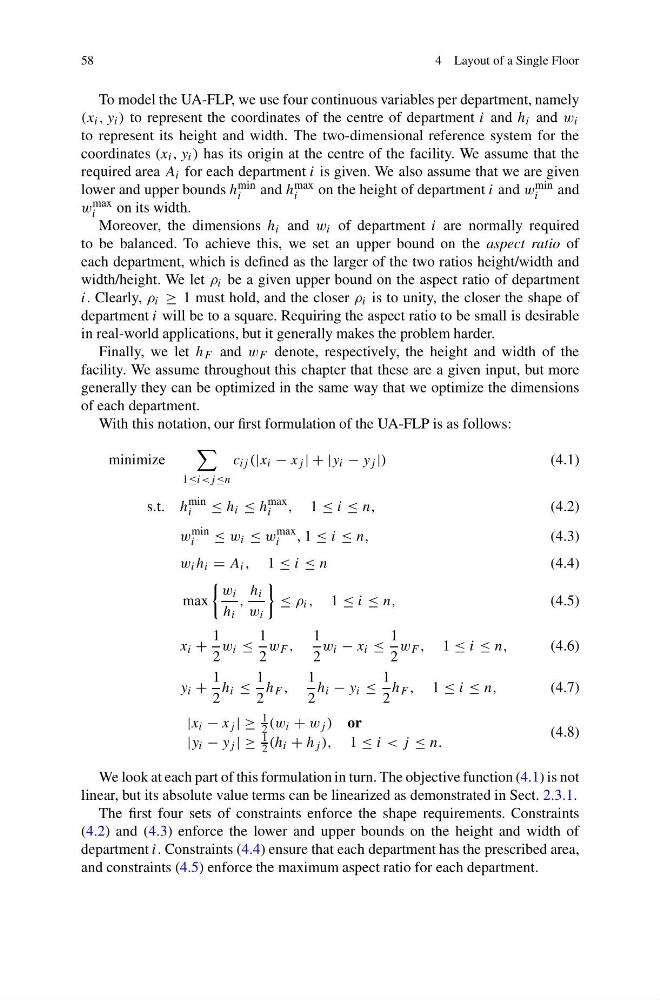
With this notation, our first formulation of the UA-FLP is as follows:
minimize
1≤i
(4.1)
s.t. h
min
i
≤ h i ≤ h
max
i , 1 ≤ i ≤ n,
(4.2)
w
min
i
≤ w i ≤ w
max
i
, 1 ≤ i ≤ n,
(4.3)
w i h i = A i , 1 ≤ i ≤ n
(4.4)
max
w i
h i
,
h i
w i
≤ ρ i , 1 ≤ i ≤ n,
(4.5)
x i +
1
2
w i ≤
1
2
w F ,
1
2
w i − x i ≤
1
2
w F , 1 ≤ i ≤ n,
(4.6)
y i +
1
2
h i ≤
1
2
h F ,
1
2
h i − y i ≤
1
2
h F , 1 ≤ i ≤ n,
(4.7)
|x i − x j | ≥
1
2 (w i + w j ) or
|y i − y j | ≥
1
2 (h i + h j ), 1 ≤ i < j ≤ n.
(4.8)
We look at each part of this formulation in turn. The objective function (4.1) is not
linear, but its absolute value terms can be linearized as demonstrated in Sect. 2.3.1.
The first four sets of constraints enforce the shape requirements. Constraints
(4.2) and (4.3) enforce the lower and upper bounds on the height and width of
department i. Constraints (4.4) ensure that each department has the prescribed area,
and constraints (4.5) enforce the maximum aspect ratio for each department.
4 Layout of a Single Floor
To model the UA-FLP, we use four continuous variables per department, namely
(x i , y i ) to represent the coordinates of the centre of department i and h i and w i
to represent its height and width. The two-dimensional reference system for the
coordinates (x i , y i ) has its origin at the centre of the facility. We assume that the
required area A i for each department i is given. We also assume that we are given
lower and upper bounds h min
i
and h max
i
on the height of department i and w min
i
and
w max
i
on its width.
Moreover, the dimensions h i and w i of department i are normally required
to be balanced. To achieve this, we set an upper bound on the aspect ratio of
each department, which is defined as the larger of the two ratios height/width and
width/height. We let ρ i be a given upper bound on the aspect ratio of department
i. Clearly, ρ i ≥ 1 must hold, and the closer ρ i is to unity, the closer the shape of
department i will be to a square. Requiring the aspect ratio to be small is desirable
in real-world applications, but it generally makes the problem harder.
Finally, we let h F and w F denote, respectively, the height and width of the
facility. We assume throughout this chapter that these are a given input, but more
generally they can be optimized in the same way that we optimize the dimensions
of each department.
With this notation, our first formulation of the UA-FLP is as follows:
minimize
1≤i
(4.1)
s.t. h
min
i
≤ h i ≤ h
max
i , 1 ≤ i ≤ n,
(4.2)
w
min
i
≤ w i ≤ w
max
i
, 1 ≤ i ≤ n,
(4.3)
w i h i = A i , 1 ≤ i ≤ n
(4.4)
max
w i
h i
,
h i
w i
≤ ρ i , 1 ≤ i ≤ n,
(4.5)
x i +
1
2
w i ≤
1
2
w F ,
1
2
w i − x i ≤
1
2
w F , 1 ≤ i ≤ n,
(4.6)
y i +
1
2
h i ≤
1
2
h F ,
1
2
h i − y i ≤
1
2
h F , 1 ≤ i ≤ n,
(4.7)
|x i − x j | ≥
1
2 (w i + w j ) or
|y i − y j | ≥
1
2 (h i + h j ), 1 ≤ i < j ≤ n.
(4.8)
We look at each part of this formulation in turn. The objective function (4.1) is not
linear, but its absolute value terms can be linearized as demonstrated in Sect. 2.3.1.
The first four sets of constraints enforce the shape requirements. Constraints
(4.2) and (4.3) enforce the lower and upper bounds on the height and width of
department i. Constraints (4.4) ensure that each department has the prescribed area,
and constraints (4.5) enforce the maximum aspect ratio for each department.