

454
10 Transport Processes
Surface of
tube (radius R)
Surface of
imaginary
cylinder
(radius r)
System of
flowing fluid
Figure 10.5 Flowing Fluid in a Tube.
The magnitude of the hydrostatic force on the liquid in the imaginary cylinder is equal
to the difference of the pressure at its ends times the cross-sectional area of the cylinder:
F h (P 2 − P 1 )πr
2
where P 2 is the pressure at one end of the tube and P 1 is the pressure at the other end.
Equating the magnitudes of F h /A and F f /A gives
(P 2 − P 1 )r
2Lη
du z
dr
du z
dr
We assume that u z is negative and conclude that du z /dr is positive since the magnitude
of the flow velocity is larger in the center of the tube. We multiply both sides of this
equation by dr and integrate from r R to r r , where R is the radius of the tube
and r is some value of r inside the tube:
r
R
du z
dr
dr
u z( r )
u z (R)
du z
P 2 − P 1
2Lη
r
R
rdr
If the liquid does not slip on the tube walls u z (R) will vanish, and the integration yields
u z (r)
P 2 − P 1
4Lη
r 2 − R 2
(10.2-23)
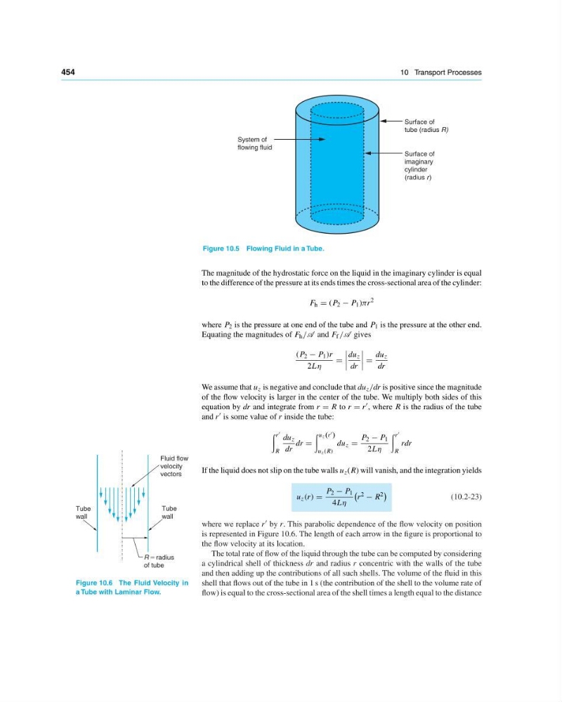
where we replace r by r. This parabolic dependence of the flow velocity on position
is represented in Figure 10.6. The length of each arrow in the figure is proportional to
the flow velocity at its location.
Tube
wall
R ϭ radius
of tube
Fluid flow
velocity
vectors
Tube
wall
Figure 10.6 The Fluid Velocity in
a Tube with Laminar Flow.
The total rate of flow of the liquid through the tube can be computed by considering
a cylindrical shell of thickness dr and radius r concentric with the walls of the tube
and then adding up the contributions of all such shells. The volume of the fluid in this
shell that flows out of the tube in 1 s (the contribution of the shell to the volume rate of
flow) is equal to the cross-sectional area of the shell times a length equal to the distance
10 Transport Processes
Surface of
tube (radius R)
Surface of
imaginary
cylinder
(radius r)
System of
flowing fluid
Figure 10.5 Flowing Fluid in a Tube.
The magnitude of the hydrostatic force on the liquid in the imaginary cylinder is equal
to the difference of the pressure at its ends times the cross-sectional area of the cylinder:
F h (P 2 − P 1 )πr
2
where P 2 is the pressure at one end of the tube and P 1 is the pressure at the other end.
Equating the magnitudes of F h /A and F f /A gives
(P 2 − P 1 )r
2Lη
du z
dr
du z
dr
We assume that u z is negative and conclude that du z /dr is positive since the magnitude
of the flow velocity is larger in the center of the tube. We multiply both sides of this
equation by dr and integrate from r R to r r , where R is the radius of the tube
and r is some value of r inside the tube:
r
R
du z
dr
dr
u z( r )
u z (R)
du z
P 2 − P 1
2Lη
r
R
rdr
If the liquid does not slip on the tube walls u z (R) will vanish, and the integration yields
u z (r)
P 2 − P 1
4Lη
r 2 − R 2
(10.2-23)
where we replace r by r. This parabolic dependence of the flow velocity on position
is represented in Figure 10.6. The length of each arrow in the figure is proportional to
the flow velocity at its location.
Tube
wall
R ϭ radius
of tube
Fluid flow
velocity
vectors
Tube
wall
Figure 10.6 The Fluid Velocity in
a Tube with Laminar Flow.
The total rate of flow of the liquid through the tube can be computed by considering
a cylindrical shell of thickness dr and radius r concentric with the walls of the tube
and then adding up the contributions of all such shells. The volume of the fluid in this
shell that flows out of the tube in 1 s (the contribution of the shell to the volume rate of
flow) is equal to the cross-sectional area of the shell times a length equal to the distance