

4 Femtosecond Photodissociation Dynamics by Velocity Map Imaging
65
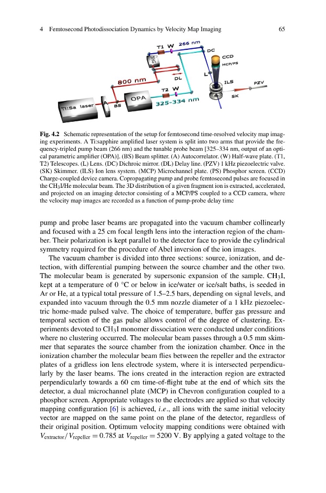
Fig. 4.2 Schematic representation of the setup for femtosecond time-resolved velocity map imaging experiments. A Ti:sapphire amplified laser system is split into two arms that provide the frequency-tripled pump beam (266 nm) and the tunable probe beam [325–334 nm, output of an optical parametric amplifier (OPA)]. (BS) Beam splitter. (A) Autocorrelator. (W) Half-wave plate. (T1,
T2) Telescopes. (L) Lens. (DC) Dichroic mirror. (DL) Delay line. (PZV) 1 kHz piezoelectric valve.
(SK) Skimmer. (ILS) Ion lens system. (MCP) Microchannel plate. (PS) Phosphor screen. (CCD)
Charge-coupled device camera. Copropagating pump and probe femtosecond pulses are focused in
the CH 3 I/He molecular beam. The 3D distribution of a given fragment ion is extracted, accelerated,
and projected on an imaging detector consisting of a MCP/PS coupled to a CCD camera, where
the velocity map images are recorded as a function of pump-probe delay time
pump and probe laser beams are propagated into the vacuum chamber collinearly
and focused with a 25 cm focal length lens into the interaction region of the chamber. Their polarization is kept parallel to the detector face to provide the cylindrical
symmetry required for the procedure of Abel inversion of the ion images.
The vacuum chamber is divided into three sections: source, ionization, and detection, with differential pumping between the source chamber and the other two.
The molecular beam is generated by supersonic expansion of the sample. CH 3 I,
kept at a temperature of 0 °C or below in ice/water or ice/salt baths, is seeded in
Ar or He, at a typical total pressure of 1.5–2.5 bars, depending on signal levels, and
expanded into vacuum through the 0.5 mm nozzle diameter of a 1 kHz piezoelectric home-made pulsed valve. The choice of temperature, buffer gas pressure and
temporal section of the gas pulse allows control of the degree of clustering. Experiments devoted to CH 3 I monomer dissociation were conducted under conditions
where no clustering occurred. The molecular beam passes through a 0.5 mm skimmer that separates the source chamber from the ionization chamber. Once in the
ionization chamber the molecular beam flies between the repeller and the extractor
plates of a gridless ion lens electrode system, where it is intersected perpendicularly by the laser beams. The ions created in the interaction region are extracted
perpendicularly towards a 60 cm time-of-flight tube at the end of which sits the
detector, a dual microchannel plate (MCP) in Chevron configuration coupled to a
phosphor screen. Appropriate voltages to the electrodes are applied so that velocity
mapping configuration [6] is achieved, i.e., all ions with the same initial velocity
vector are mapped on the same point on the plane of the detector, regardless of
their original position. Optimum velocity mapping conditions were obtained with
V extractor /V repeller = 0.785 at V repeller = 5200 V. By applying a gated voltage to the
65
Fig. 4.2 Schematic representation of the setup for femtosecond time-resolved velocity map imaging experiments. A Ti:sapphire amplified laser system is split into two arms that provide the frequency-tripled pump beam (266 nm) and the tunable probe beam [325–334 nm, output of an optical parametric amplifier (OPA)]. (BS) Beam splitter. (A) Autocorrelator. (W) Half-wave plate. (T1,
T2) Telescopes. (L) Lens. (DC) Dichroic mirror. (DL) Delay line. (PZV) 1 kHz piezoelectric valve.
(SK) Skimmer. (ILS) Ion lens system. (MCP) Microchannel plate. (PS) Phosphor screen. (CCD)
Charge-coupled device camera. Copropagating pump and probe femtosecond pulses are focused in
the CH 3 I/He molecular beam. The 3D distribution of a given fragment ion is extracted, accelerated,
and projected on an imaging detector consisting of a MCP/PS coupled to a CCD camera, where
the velocity map images are recorded as a function of pump-probe delay time
pump and probe laser beams are propagated into the vacuum chamber collinearly
and focused with a 25 cm focal length lens into the interaction region of the chamber. Their polarization is kept parallel to the detector face to provide the cylindrical
symmetry required for the procedure of Abel inversion of the ion images.
The vacuum chamber is divided into three sections: source, ionization, and detection, with differential pumping between the source chamber and the other two.
The molecular beam is generated by supersonic expansion of the sample. CH 3 I,
kept at a temperature of 0 °C or below in ice/water or ice/salt baths, is seeded in
Ar or He, at a typical total pressure of 1.5–2.5 bars, depending on signal levels, and
expanded into vacuum through the 0.5 mm nozzle diameter of a 1 kHz piezoelectric home-made pulsed valve. The choice of temperature, buffer gas pressure and
temporal section of the gas pulse allows control of the degree of clustering. Experiments devoted to CH 3 I monomer dissociation were conducted under conditions
where no clustering occurred. The molecular beam passes through a 0.5 mm skimmer that separates the source chamber from the ionization chamber. Once in the
ionization chamber the molecular beam flies between the repeller and the extractor
plates of a gridless ion lens electrode system, where it is intersected perpendicularly by the laser beams. The ions created in the interaction region are extracted
perpendicularly towards a 60 cm time-of-flight tube at the end of which sits the
detector, a dual microchannel plate (MCP) in Chevron configuration coupled to a
phosphor screen. Appropriate voltages to the electrodes are applied so that velocity
mapping configuration [6] is achieved, i.e., all ions with the same initial velocity
vector are mapped on the same point on the plane of the detector, regardless of
their original position. Optimum velocity mapping conditions were obtained with
V extractor /V repeller = 0.785 at V repeller = 5200 V. By applying a gated voltage to the