

8 Ultrafast Ionization and Fragmentation: From Small Molecules
179
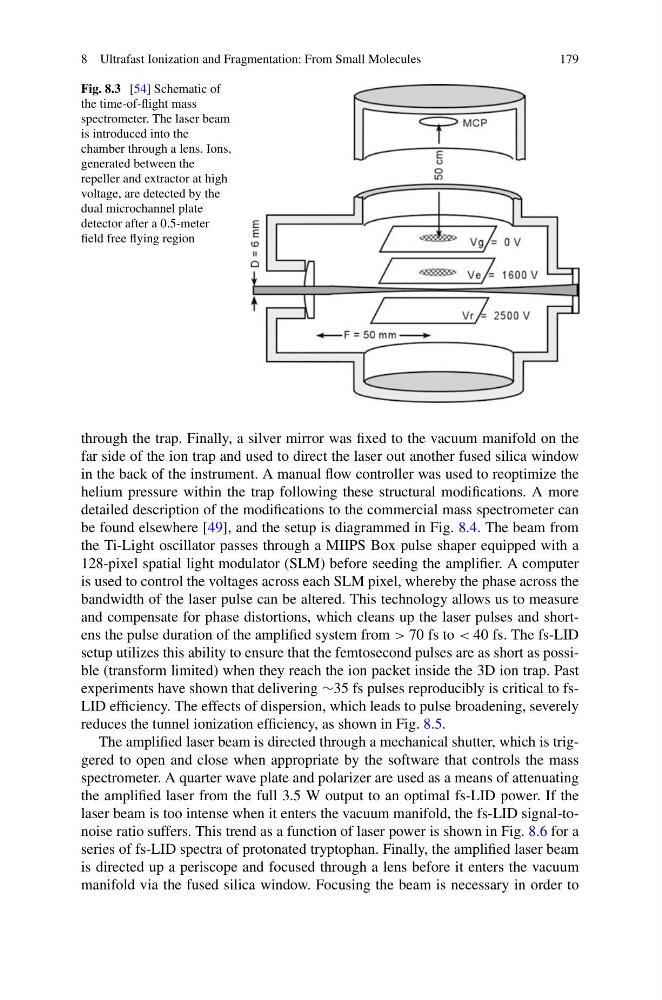
Fig. 8.3 [54] Schematic of
the time-of-flight mass
spectrometer. The laser beam
is introduced into the
chamber through a lens. Ions,
generated between the
repeller and extractor at high
voltage, are detected by the
dual microchannel plate
detector after a 0.5-meter
field free flying region
through the trap. Finally, a silver mirror was fixed to the vacuum manifold on the
far side of the ion trap and used to direct the laser out another fused silica window
in the back of the instrument. A manual flow controller was used to reoptimize the
helium pressure within the trap following these structural modifications. A more
detailed description of the modifications to the commercial mass spectrometer can
be found elsewhere [49], and the setup is diagrammed in Fig. 8.4. The beam from
the Ti-Light oscillator passes through a MIIPS Box pulse shaper equipped with a
128-pixel spatial light modulator (SLM) before seeding the amplifier. A computer
is used to control the voltages across each SLM pixel, whereby the phase across the
bandwidth of the laser pulse can be altered. This technology allows us to measure
and compensate for phase distortions, which cleans up the laser pulses and shortens the pulse duration of the amplified system from > 70 fs to < 40 fs. The fs-LID
setup utilizes this ability to ensure that the femtosecond pulses are as short as possible (transform limited) when they reach the ion packet inside the 3D ion trap. Past
experiments have shown that delivering ∼35 fs pulses reproducibly is critical to fsLID efficiency. The effects of dispersion, which leads to pulse broadening, severely
reduces the tunnel ionization efficiency, as shown in Fig. 8.5.
The amplified laser beam is directed through a mechanical shutter, which is triggered to open and close when appropriate by the software that controls the mass
spectrometer. A quarter wave plate and polarizer are used as a means of attenuating
the amplified laser from the full 3.5 W output to an optimal fs-LID power. If the
laser beam is too intense when it enters the vacuum manifold, the fs-LID signal-tonoise ratio suffers. This trend as a function of laser power is shown in Fig. 8.6 for a
series of fs-LID spectra of protonated tryptophan. Finally, the amplified laser beam
is directed up a periscope and focused through a lens before it enters the vacuum
manifold via the fused silica window. Focusing the beam is necessary in order to
179
Fig. 8.3 [54] Schematic of
the time-of-flight mass
spectrometer. The laser beam
is introduced into the
chamber through a lens. Ions,
generated between the
repeller and extractor at high
voltage, are detected by the
dual microchannel plate
detector after a 0.5-meter
field free flying region
through the trap. Finally, a silver mirror was fixed to the vacuum manifold on the
far side of the ion trap and used to direct the laser out another fused silica window
in the back of the instrument. A manual flow controller was used to reoptimize the
helium pressure within the trap following these structural modifications. A more
detailed description of the modifications to the commercial mass spectrometer can
be found elsewhere [49], and the setup is diagrammed in Fig. 8.4. The beam from
the Ti-Light oscillator passes through a MIIPS Box pulse shaper equipped with a
128-pixel spatial light modulator (SLM) before seeding the amplifier. A computer
is used to control the voltages across each SLM pixel, whereby the phase across the
bandwidth of the laser pulse can be altered. This technology allows us to measure
and compensate for phase distortions, which cleans up the laser pulses and shortens the pulse duration of the amplified system from > 70 fs to < 40 fs. The fs-LID
setup utilizes this ability to ensure that the femtosecond pulses are as short as possible (transform limited) when they reach the ion packet inside the 3D ion trap. Past
experiments have shown that delivering ∼35 fs pulses reproducibly is critical to fsLID efficiency. The effects of dispersion, which leads to pulse broadening, severely
reduces the tunnel ionization efficiency, as shown in Fig. 8.5.
The amplified laser beam is directed through a mechanical shutter, which is triggered to open and close when appropriate by the software that controls the mass
spectrometer. A quarter wave plate and polarizer are used as a means of attenuating
the amplified laser from the full 3.5 W output to an optimal fs-LID power. If the
laser beam is too intense when it enters the vacuum manifold, the fs-LID signal-tonoise ratio suffers. This trend as a function of laser power is shown in Fig. 8.6 for a
series of fs-LID spectra of protonated tryptophan. Finally, the amplified laser beam
is directed up a periscope and focused through a lens before it enters the vacuum
manifold via the fused silica window. Focusing the beam is necessary in order to