

4
2 Layout on a Single Row
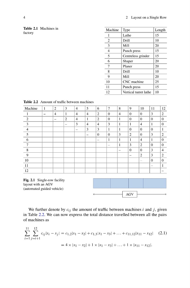
Table 2.1 Machines in
factory
Machine Type
Length
1
Lathe
15
2
Drill
10
3
Mill
20
4
Punch press
15
5
Centreless grinder
15
6
Shaper
20
7
Planer
20
8
Drill
10
9
Mill
20
10
CNC machine
25
11
Punch press
15
12
Vertical turret lathe 10
Table 2.2 Amount of traffic between machines
Machine
1
2
3
4
5
6
7
8
9
10
11
12
1
–
4
1
4
4
2
0
4
0
0
3
2
2
–
2
4
1
2
0
1
0
0
0
0
3
–
3
4
4
3
1
1
4
1
0
4
–
3
3
1
1
0
0
0
1
5
–
0
0
3
2
0
3
2
6
–
1
1
1
4
1
0
7
–
1
3
2
0
0
8
–
0
0
3
4
9
–
2
3
2
10
–
0
0
11
–
1
12
–
Fig. 2.1 Single-row facility
layout with an AGV
(automated guided vehicle)
AGV
We further denote by c ij the amount of traffic between machines i and j , given
in Table 2.2. We can now express the total distance travelled between all the pairs
of machines as
11
i=1
12
j =i+1
c ij |x i − x j | = c 1,2 |x 1 − x 2 | + c 1,3 |x 1 − x 3 | + . . . + c 11,12 |x 11 − x 12 | (2.1)
= 4 × |x 1 − x 2 | + 1 × |x 1 − x 3 | + . . . + 1 × |x 11 − x 12 |.
2 Layout on a Single Row
Table 2.1 Machines in
factory
Machine Type
Length
1
Lathe
15
2
Drill
10
3
Mill
20
4
Punch press
15
5
Centreless grinder
15
6
Shaper
20
7
Planer
20
8
Drill
10
9
Mill
20
10
CNC machine
25
11
Punch press
15
12
Vertical turret lathe 10
Table 2.2 Amount of traffic between machines
Machine
1
2
3
4
5
6
7
8
9
10
11
12
1
–
4
1
4
4
2
0
4
0
0
3
2
2
–
2
4
1
2
0
1
0
0
0
0
3
–
3
4
4
3
1
1
4
1
0
4
–
3
3
1
1
0
0
0
1
5
–
0
0
3
2
0
3
2
6
–
1
1
1
4
1
0
7
–
1
3
2
0
0
8
–
0
0
3
4
9
–
2
3
2
10
–
0
0
11
–
1
12
–
Fig. 2.1 Single-row facility
layout with an AGV
(automated guided vehicle)
AGV
We further denote by c ij the amount of traffic between machines i and j , given
in Table 2.2. We can now express the total distance travelled between all the pairs
of machines as
11
i=1
12
j =i+1
c ij |x i − x j | = c 1,2 |x 1 − x 2 | + c 1,3 |x 1 − x 3 | + . . . + c 11,12 |x 11 − x 12 | (2.1)
= 4 × |x 1 − x 2 | + 1 × |x 1 − x 3 | + . . . + 1 × |x 11 − x 12 |.