

64
Z. Amini et al.
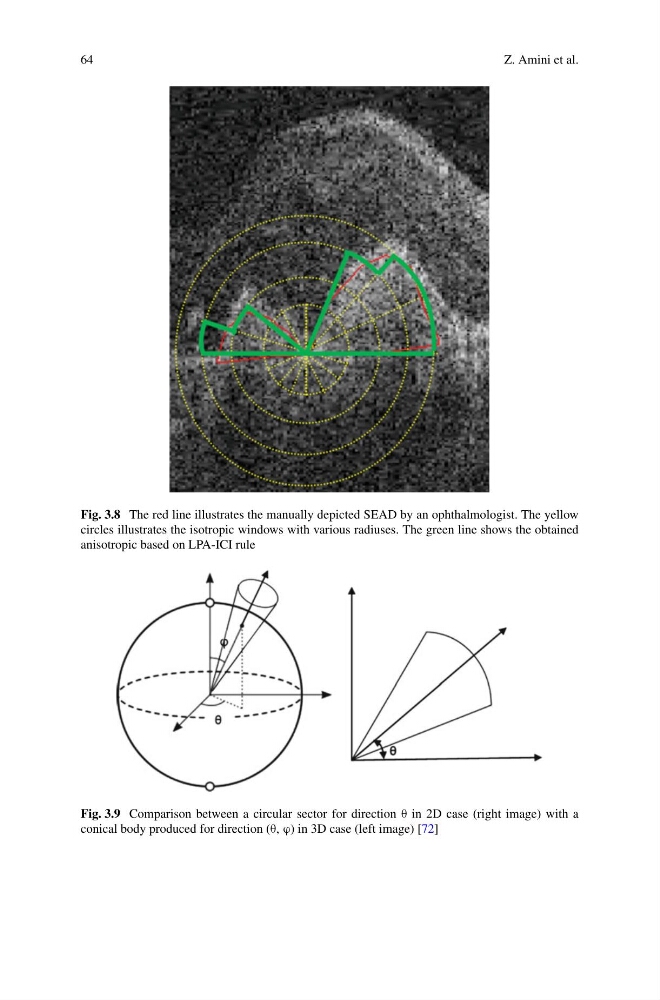
Fig. 3.8 The red line illustrates the manually depicted SEAD by an ophthalmologist. The yellow
circles illustrates the isotropic windows with various radiuses. The green line shows the obtained
anisotropic based on LPA-ICI rule
Fig. 3.9 Comparison between a circular sector for direction θ in 2D case (right image) with a
conical body produced for direction (θ, ϕ) in 3D case (left image) [72]
Z. Amini et al.
Fig. 3.8 The red line illustrates the manually depicted SEAD by an ophthalmologist. The yellow
circles illustrates the isotropic windows with various radiuses. The green line shows the obtained
anisotropic based on LPA-ICI rule
Fig. 3.9 Comparison between a circular sector for direction θ in 2D case (right image) with a
conical body produced for direction (θ, ϕ) in 3D case (left image) [72]