

F.1
F
Derivations for DC-DC converters
As we have discussed in Section 19.2.2, a DC-DC converter is an electronic circuit which
converts a source of direct current from one voltage level to another. An ideal PV
converter should draw the maximum power from the PV panel and supply at the load side.
We discussed three types of DC-DC converters: buck converters that convert voltage from
a higher to a lower level, boost converter that convert voltage from a lower to a higher
level, and buck-boost converters, which can perform both operations. In this Appendix, we
will derive important relations for these three types in more detail.
Buck converter
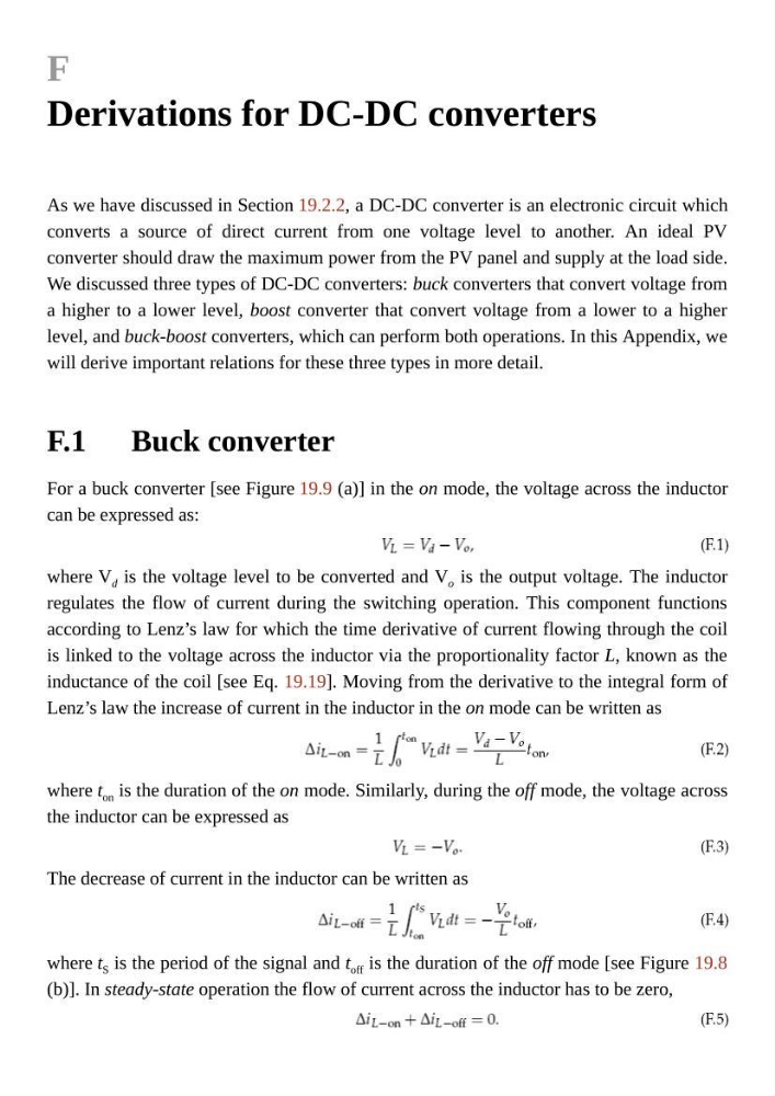
For a buck converter [see Figure 19.9 (a)] in the on mode, the voltage across the inductor
can be expressed as:
where V d is the voltage level to be converted and V o is the output voltage. The inductor
regulates the flow of current during the switching operation. This component functions
according to Lenz’s law for which the time derivative of current flowing through the coil
is linked to the voltage across the inductor via the proportionality factor L, known as the
inductance of the coil [see Eq. 19.19]. Moving from the derivative to the integral form of
Lenz’s law the increase of current in the inductor in the on mode can be written as
where t on is the duration of the on mode. Similarly, during the off mode, the voltage across
the inductor can be expressed as
The decrease of current in the inductor can be written as
where t S is the period of the signal and t off is the duration of the off mode [see Figure 19.8
(b)]. In steady-state operation the flow of current across the inductor has to be zero,
F
Derivations for DC-DC converters
As we have discussed in Section 19.2.2, a DC-DC converter is an electronic circuit which
converts a source of direct current from one voltage level to another. An ideal PV
converter should draw the maximum power from the PV panel and supply at the load side.
We discussed three types of DC-DC converters: buck converters that convert voltage from
a higher to a lower level, boost converter that convert voltage from a lower to a higher
level, and buck-boost converters, which can perform both operations. In this Appendix, we
will derive important relations for these three types in more detail.
Buck converter
For a buck converter [see Figure 19.9 (a)] in the on mode, the voltage across the inductor
can be expressed as:
where V d is the voltage level to be converted and V o is the output voltage. The inductor
regulates the flow of current during the switching operation. This component functions
according to Lenz’s law for which the time derivative of current flowing through the coil
is linked to the voltage across the inductor via the proportionality factor L, known as the
inductance of the coil [see Eq. 19.19]. Moving from the derivative to the integral form of
Lenz’s law the increase of current in the inductor in the on mode can be written as
where t on is the duration of the on mode. Similarly, during the off mode, the voltage across
the inductor can be expressed as
The decrease of current in the inductor can be written as
where t S is the period of the signal and t off is the duration of the off mode [see Figure 19.8
(b)]. In steady-state operation the flow of current across the inductor has to be zero,