

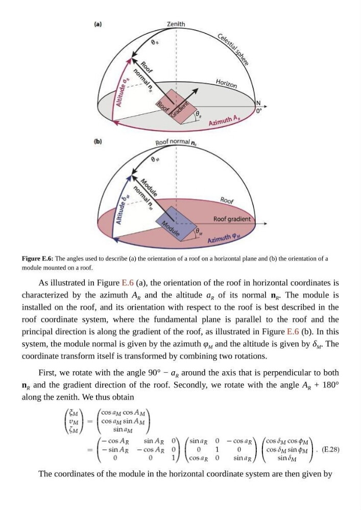
Figure E.6: The angles used to describe (a) the orientation of a roof on a horizontal plane and (b) the orientation of a
module mounted on a roof.
As illustrated in Figure E.6 (a), the orientation of the roof in horizontal coordinates is
characterized by the azimuth A R and the altitude a R of its normal n R . The module is
installed on the roof, and its orientation with respect to the roof is best described in the
roof coordinate system, where the fundamental plane is parallel to the roof and the
principal direction is along the gradient of the roof, as illustrated in Figure E.6 (b). In this
system, the module normal is given by the azimuth φ M and the altitude is given by δ M . The
coordinate transform itself is transformed by combining two rotations.
First, we rotate with the angle 90° − a R around the axis that is perpendicular to both
n R and the gradient direction of the roof. Secondly, we rotate with the angle A R + 180°
along the zenith. We thus obtain
The coordinates of the module in the horizontal coordinate system are then given by
module mounted on a roof.
As illustrated in Figure E.6 (a), the orientation of the roof in horizontal coordinates is
characterized by the azimuth A R and the altitude a R of its normal n R . The module is
installed on the roof, and its orientation with respect to the roof is best described in the
roof coordinate system, where the fundamental plane is parallel to the roof and the
principal direction is along the gradient of the roof, as illustrated in Figure E.6 (b). In this
system, the module normal is given by the azimuth φ M and the altitude is given by δ M . The
coordinate transform itself is transformed by combining two rotations.
First, we rotate with the angle 90° − a R around the axis that is perpendicular to both
n R and the gradient direction of the roof. Secondly, we rotate with the angle A R + 180°
along the zenith. We thus obtain
The coordinates of the module in the horizontal coordinate system are then given by