

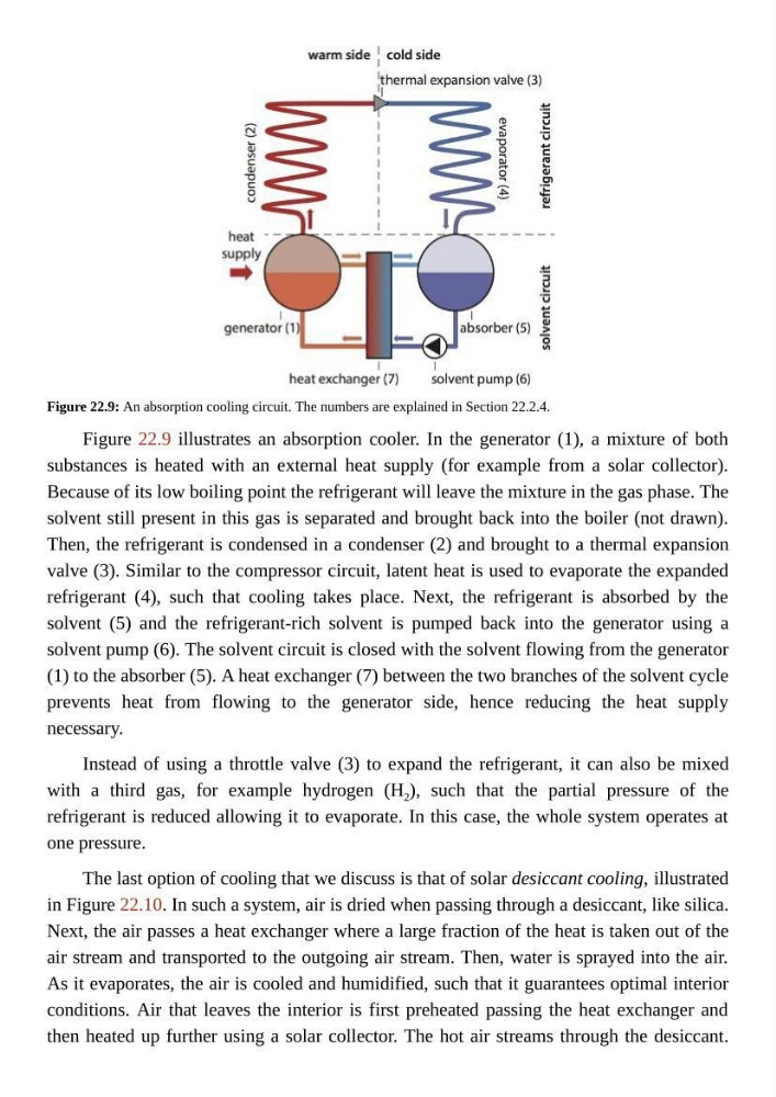
Figure 22.9: An absorption cooling circuit. The numbers are explained in Section 22.2.4.
Figure 22.9 illustrates an absorption cooler. In the generator (1), a mixture of both
substances is heated with an external heat supply (for example from a solar collector).
Because of its low boiling point the refrigerant will leave the mixture in the gas phase. The
solvent still present in this gas is separated and brought back into the boiler (not drawn).
Then, the refrigerant is condensed in a condenser (2) and brought to a thermal expansion
valve (3). Similar to the compressor circuit, latent heat is used to evaporate the expanded
refrigerant (4), such that cooling takes place. Next, the refrigerant is absorbed by the
solvent (5) and the refrigerant-rich solvent is pumped back into the generator using a
solvent pump (6). The solvent circuit is closed with the solvent flowing from the generator
(1) to the absorber (5). A heat exchanger (7) between the two branches of the solvent cycle
prevents heat from flowing to the generator side, hence reducing the heat supply
necessary.
Instead of using a throttle valve (3) to expand the refrigerant, it can also be mixed
with a third gas, for example hydrogen (H 2 ), such that the partial pressure of the
refrigerant is reduced allowing it to evaporate. In this case, the whole system operates at
one pressure.
The last option of cooling that we discuss is that of solar desiccant cooling, illustrated
in Figure 22.10. In such a system, air is dried when passing through a desiccant, like silica.
Next, the air passes a heat exchanger where a large fraction of the heat is taken out of the
air stream and transported to the outgoing air stream. Then, water is sprayed into the air.
As it evaporates, the air is cooled and humidified, such that it guarantees optimal interior
conditions. Air that leaves the interior is first preheated passing the heat exchanger and
then heated up further using a solar collector. The hot air streams through the desiccant.
Figure 22.9 illustrates an absorption cooler. In the generator (1), a mixture of both
substances is heated with an external heat supply (for example from a solar collector).
Because of its low boiling point the refrigerant will leave the mixture in the gas phase. The
solvent still present in this gas is separated and brought back into the boiler (not drawn).
Then, the refrigerant is condensed in a condenser (2) and brought to a thermal expansion
valve (3). Similar to the compressor circuit, latent heat is used to evaporate the expanded
refrigerant (4), such that cooling takes place. Next, the refrigerant is absorbed by the
solvent (5) and the refrigerant-rich solvent is pumped back into the generator using a
solvent pump (6). The solvent circuit is closed with the solvent flowing from the generator
(1) to the absorber (5). A heat exchanger (7) between the two branches of the solvent cycle
prevents heat from flowing to the generator side, hence reducing the heat supply
necessary.
Instead of using a throttle valve (3) to expand the refrigerant, it can also be mixed
with a third gas, for example hydrogen (H 2 ), such that the partial pressure of the
refrigerant is reduced allowing it to evaporate. In this case, the whole system operates at
one pressure.
The last option of cooling that we discuss is that of solar desiccant cooling, illustrated
in Figure 22.10. In such a system, air is dried when passing through a desiccant, like silica.
Next, the air passes a heat exchanger where a large fraction of the heat is taken out of the
air stream and transported to the outgoing air stream. Then, water is sprayed into the air.
As it evaporates, the air is cooled and humidified, such that it guarantees optimal interior
conditions. Air that leaves the interior is first preheated passing the heat exchanger and
then heated up further using a solar collector. The hot air streams through the desiccant.