

20.5.1
Telecommunications
10 −4
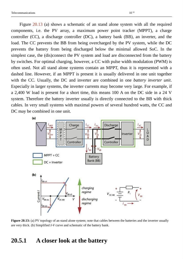
Figure 20.13 (a) shows a schematic of an stand alone system with all the required
components, i.e. the PV array, a maximum power point tracker (MPPT), a charge
controller (CC), a discharge controller (DC), a battery bank (BB), an inverter, and the
load. The CC prevents the BB from being overcharged by the PV system, while the DC
prevents the battery from being discharged below the minimal allowed SoC. In the
simplest case, the (dis)connect the PV system and load are disconnected from the battery
by switches. For optimal charging, however, a CC with pulse width modulation (PWM) is
often used. Not all stand alone systems contain an MPPT, thus it is represented with a
dashed line. However, if an MPPT is present it is usually delivered in one unit together
with the CC. Usually, the DC and inverter are combined in one battery inverter unit.
Especially in larger systems, the inverter currents may become very large. For example, if
a 2,400 W load is present for a short time, this means 100 A on the DC side in a 24 V
system. Therefore the battery inverter usually is directly connected to the BB with thick
cables. In very small systems with maximal powers of several hundred watts, the CC and
DC may be combined in one unit.
Figure 20.13: (a) PV topology of an stand alone system; note that cables between the batteries and the inverter usually
are very thick. (b) Simplified I-V curve and schematic of the battery bank.
A closer look at the battery
Telecommunications
10 −4
Figure 20.13 (a) shows a schematic of an stand alone system with all the required
components, i.e. the PV array, a maximum power point tracker (MPPT), a charge
controller (CC), a discharge controller (DC), a battery bank (BB), an inverter, and the
load. The CC prevents the BB from being overcharged by the PV system, while the DC
prevents the battery from being discharged below the minimal allowed SoC. In the
simplest case, the (dis)connect the PV system and load are disconnected from the battery
by switches. For optimal charging, however, a CC with pulse width modulation (PWM) is
often used. Not all stand alone systems contain an MPPT, thus it is represented with a
dashed line. However, if an MPPT is present it is usually delivered in one unit together
with the CC. Usually, the DC and inverter are combined in one battery inverter unit.
Especially in larger systems, the inverter currents may become very large. For example, if
a 2,400 W load is present for a short time, this means 100 A on the DC side in a 24 V
system. Therefore the battery inverter usually is directly connected to the BB with thick
cables. In very small systems with maximal powers of several hundred watts, the CC and
DC may be combined in one unit.
Figure 20.13: (a) PV topology of an stand alone system; note that cables between the batteries and the inverter usually
are very thick. (b) Simplified I-V curve and schematic of the battery bank.
A closer look at the battery