

25
Contemporary Machining Processes
and partial vaporization of a workpiece) produced by series of sparks occurring
between the electrode and workpiece (Hourmand et al., 2017). The EDM process is
potentially useful for machining materials with various hardness, complex shapes,
strength, and temperature resistance.
EDM enables the machining of extremely hard materials, whereby complex
shapes can be produced with high precision. Its inherent capability for automation is
another feature fulfilling expectations of modern manufacturing. For these reasons,
electrical discharge machining has become the most popular, nontraditional material
removal process in today’s manufacturing practice (Lauwers et al., 2012).
Two main EDM techniques may be distinguished, namely die-sinking EDM and
wire cutting EDM. The die-sinking EDM uses an electrode to plunge into a workpiece and create a negative shape of the electrode, while the wire EDM utilizes a uniform wire that moves continuously and gradually cuts through a workpiece (Izwan
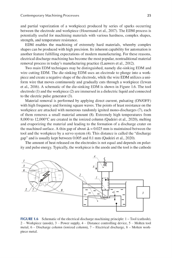
et al., 2016). A schematic of the die-sinking EDM is shown in Figure 1.6. The tool
electrode (1) and the workpiece (2) are immersed in a dielectric liquid and connected
to the electric pulse generator (3).
Material removal is performed by applying direct current, pulsating (ON/OFF)
with high frequency and forming square waves. The points of least resistance on the
workpiece are attacked with numerous randomly ignited mono-discharges (7), each
of them removes a small material amount (8). Extremely high temperatures from
8,000 to 12,000°C are created in the ionized column (Qudeiri et al., 2020), melting
and evaporizing the material and leading to the formation of a discharge crater on
the machined surface. A thin gap of about Δ = 0.025 mm is maintained between the
tool and the workpiece by a servo system (4). This distance is called the “discharge
gap” and is usually kept between 0.005 and 0.1 mm (Qudeiri et al., 2020).
The amount of heat released on the electrodes is not equal and depends on polarity and pulse energy. Typically, the workpiece is the anode and the tool is the cathode
FIGURE 1.6 Schematic of the electrical discharge machining principle: 1 – Tool (cathode),
2 – Workpiece (anode), 3 – Power supply, 4 – Distance controlling device, 5 – Molten tool
metal, 6 – Discharge column (ionized column), 7 – Electrical discharge, 8 – Molten workpiece metal.
Contemporary Machining Processes
and partial vaporization of a workpiece) produced by series of sparks occurring
between the electrode and workpiece (Hourmand et al., 2017). The EDM process is
potentially useful for machining materials with various hardness, complex shapes,
strength, and temperature resistance.
EDM enables the machining of extremely hard materials, whereby complex
shapes can be produced with high precision. Its inherent capability for automation is
another feature fulfilling expectations of modern manufacturing. For these reasons,
electrical discharge machining has become the most popular, nontraditional material
removal process in today’s manufacturing practice (Lauwers et al., 2012).
Two main EDM techniques may be distinguished, namely die-sinking EDM and
wire cutting EDM. The die-sinking EDM uses an electrode to plunge into a workpiece and create a negative shape of the electrode, while the wire EDM utilizes a uniform wire that moves continuously and gradually cuts through a workpiece (Izwan
et al., 2016). A schematic of the die-sinking EDM is shown in Figure 1.6. The tool
electrode (1) and the workpiece (2) are immersed in a dielectric liquid and connected
to the electric pulse generator (3).
Material removal is performed by applying direct current, pulsating (ON/OFF)
with high frequency and forming square waves. The points of least resistance on the
workpiece are attacked with numerous randomly ignited mono-discharges (7), each
of them removes a small material amount (8). Extremely high temperatures from
8,000 to 12,000°C are created in the ionized column (Qudeiri et al., 2020), melting
and evaporizing the material and leading to the formation of a discharge crater on
the machined surface. A thin gap of about Δ = 0.025 mm is maintained between the
tool and the workpiece by a servo system (4). This distance is called the “discharge
gap” and is usually kept between 0.005 and 0.1 mm (Qudeiri et al., 2020).
The amount of heat released on the electrodes is not equal and depends on polarity and pulse energy. Typically, the workpiece is the anode and the tool is the cathode
FIGURE 1.6 Schematic of the electrical discharge machining principle: 1 – Tool (cathode),
2 – Workpiece (anode), 3 – Power supply, 4 – Distance controlling device, 5 – Molten tool
metal, 6 – Discharge column (ionized column), 7 – Electrical discharge, 8 – Molten workpiece metal.