

616
The Chemistry and Technology of Petroleum
22.3.17 resIdue HydroConversIon ProCess
The residue hydroconversion process (RHC process) is a high-pressure fixed-bed trickle-flow
hydrocatalytic process (RAROP, 1991, p. 71; Robschalager et al., 1992). The feedstock can be
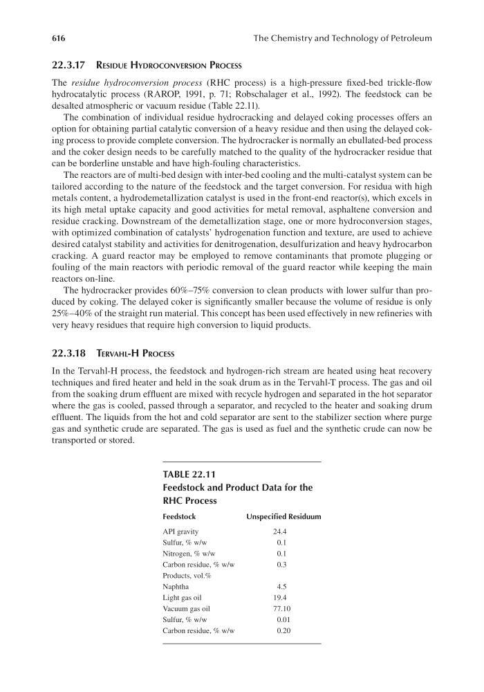
desalted atmospheric or vacuum residue (Table 22.11).
The combination of individual residue hydrocracking and delayed coking processes offers an
option for obtaining partial catalytic conversion of a heavy residue and then using the delayed coking process to provide complete conversion. The hydrocracker is normally an ebullated-bed process
and the coker design needs to be carefully matched to the quality of the hydrocracker residue that
can be borderline unstable and have high-fouling characteristics.
The reactors are of multi-bed design with inter-bed cooling and the multi-catalyst system can be
tailored according to the nature of the feedstock and the target conversion. For residua with high
metals content, a hydrodemetallization catalyst is used in the front-end reactor(s), which excels in
its high metal uptake capacity and good activities for metal removal, asphaltene conversion and
residue cracking. Downstream of the demetallization stage, one or more hydroconversion stages,
with optimized combination of catalysts’ hydrogenation function and texture, are used to achieve
desired catalyst stability and activities for denitrogenation, desulfurization and heavy hydrocarbon
cracking. A guard reactor may be employed to remove contaminants that promote plugging or
fouling of the main reactors with periodic removal of the guard reactor while keeping the main
reactors on-line.
The hydrocracker provides 60%–75% conversion to clean products with lower sulfur than produced by coking. The delayed coker is significantly smaller because the volume of residue is only
25%–40% of the straight run material. This concept has been used effectively in new refineries with
very heavy residues that require high conversion to liquid products.
22.3.18 tervAHl-H ProCess
In the Tervahl-H process, the feedstock and hydrogen-rich stream are heated using heat recovery
techniques and fired heater and held in the soak drum as in the Tervahl-T process. The gas and oil
from the soaking drum effluent are mixed with recycle hydrogen and separated in the hot separator
where the gas is cooled, passed through a separator, and recycled to the heater and soaking drum
effluent. The liquids from the hot and cold separator are sent to the stabilizer section where purge
gas and synthetic crude are separated. The gas is used as fuel and the synthetic crude can now be
transported or stored.
TABLE 22.11
Feedstock and Product Data for the
RHC Process
Feedstock
Unspecified Residuum
API gravity
24.4
Sulfur, % w/w
0.1
Nitrogen, % w/w
0.1
Carbon residue, % w/w
0.3
Products, vol.%
Naphtha
4.5
Light gas oil
19.4
Vacuum gas oil
77.10
Sulfur, % w/w
0.01
Carbon residue, % w/w
0.20