

528
The Chemistry and Technology of Petroleum
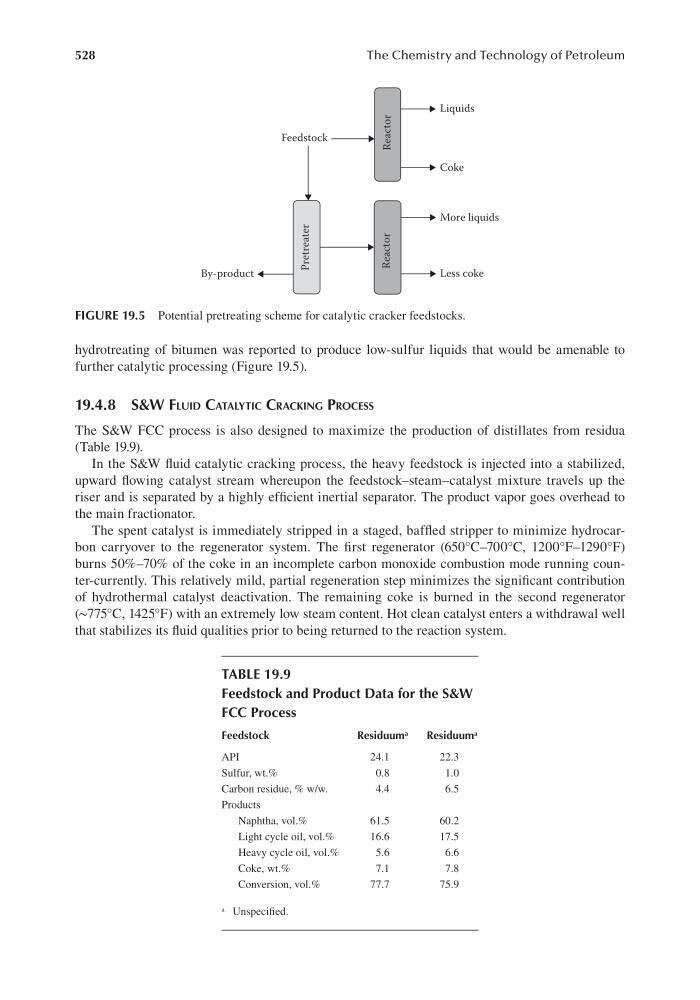
hydrotreating of bitumen was reported to produce low-sulfur liquids that would be amenable to
further catalytic processing (Figure 19.5).
19.4.8 s&W FluId CAtAlytIC CrACkIng ProCess
The S&W FCC process is also designed to maximize the production of distillates from residua
(Table 19.9).
In the S&W fluid catalytic cracking process, the heavy feedstock is injected into a stabilized,
upward flowing catalyst stream whereupon the feedstock–steam–catalyst mixture travels up the
riser and is separated by a highly efficient inertial separator. The product vapor goes overhead to
the main fractionator.
The spent catalyst is immediately stripped in a staged, baffled stripper to minimize hydrocarbon carryover to the regenerator system. The first regenerator (650°C–700°C, 1200°F–1290°F)
burns 50%–70% of the coke in an incomplete carbon monoxide combustion mode running counter-currently. This relatively mild, partial regeneration step minimizes the significant contribution
of hydrothermal catalyst deactivation. The remaining coke is burned in the second regenerator
(∼775°C, 1425°F) with an extremely low steam content. Hot clean catalyst enters a withdrawal well
that stabilizes its fluid qualities prior to being returned to the reaction system.
Feedstock
By-product
Liquids
Reactor
Reactor
Pretreater
Coke
More liquids
Less coke
FIGURE 19.5 Potential pretreating scheme for catalytic cracker feedstocks.
TABLE 19.9
Feedstock and Product Data for the S&W
FCC Process
Feedstock
Residuum a
Residuum a
API
24.1
22.3
Sulfur, wt.%
0.8
1.0
Carbon residue, % w/w.
4.4
6.5
Products
Naphtha, vol.%
61.5
60.2
Light cycle oil, vol.%
16.6
17.5
Heavy cycle oil, vol.%
5.6
6.6
Coke, wt.%
7.1
7.8
Conversion, vol.%
77.7
75.9
a Unspecified.