

519
Catalytic Cracking
The model IV low-elevation design was preceded by the model III (1947) balanced-pressure
design, the model II (1944) downflow design, and the original model I (1941) upflow design. The
first commercial model IV installation in the United States was placed on-stream in 1952.
19.3.2.3 Orthoflow Fluid-Bed Catalytic Cracking
This process uses the unitary vessel design, which provides a straight-line flow of catalyst and thereby
minimizes the erosion encountered in pipe bends. Commercial Orthoflow designs are of three types:
models A and C, with the regenerator beneath the reactor, and model B, with the regenerator above
the reactor. In all cases, the catalyst-stripping section is located between the reactor and the regenerator. All designs employ the heat-balanced principle incorporating fresh feed-recycle feed cracking.
Catalyst
stripper
Steam
S p e n t
c a t a l y s t
Flue gas to particulates
Removal and energy recovery
Reactor or
separation vessel
Riser
R e g e n e r a t e d
c a t a ly s t
Regenerator
Combustion air
Raw oil charge
Light gas oil
Gasoline
Gas (C 4 + lighter)
Fractionator
Heavy gas oil
Crude
oil
Clarified slurry
Slurry
settler
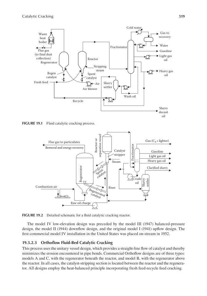
FIGURE 19.2 Detailed schematic for a fluid catalytic cracking reactor.
Cold water
Gas to
recovery
Water
Gasoline
Light gas
oil
Heavy gas
oil
Wash oil
Fractionator
Reactor
Stripping
steam
Spent
catalyst
Air blower
Slurry
settler
Regen
catalyst
Waste
heat
boiler
Flue gas
(to final dust
collection)
Regenerator
Fresh feed
Air
Recycle
Slurry
decant
oil
FIGURE 19.1 Fluid catalytic cracking process.