

152
The Chemistry and Technology of Petroleum
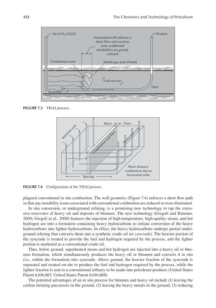
plagued conventional in situ combustion. The well geometry (Figure 7.4) enforces a short flow path
so that any instability issues associated with conventional combustion are reduced or even eliminated.
In situ conversion, or underground refining, is a promising new technology to tap the extensive reservoirs of heavy oil and deposits of bitumen. The new technology (Gregoli and Rimmer,
2000; Gregoli et al., 2000) features the injection of high-temperature, high-quality steam, and hot
hydrogen are into a formation containing heavy hydrocarbons to initiate conversion of the heavy
hydrocarbons into lighter hydrocarbons. In effect, the heavy hydrocarbons undergo partial underground refining that converts them into a synthetic crude oil (or syncrude). The heavier portion of
the syncrude is treated to provide the fuel and hydrogen required by the process, and the lighter
portion is marketed as a conventional crude oil.
Thus, below ground, superheated steam and hot hydrogen are injected into a heavy oil or bitumen formation, which simultaneously produces the heavy oil or bitumen and converts it in situ
(i.e., within the formation) into syncrude. Above ground, the heavier fraction of the syncrude is
separated and treated on-site to produce the fuel and hydrogen required by the process, while the
lighter fraction is sent to a conventional refinery to be made into petroleum products (United States
Patent 6,016,867; United States Patent 6,016,868).
The potential advantages of an in situ process for bitumen and heavy oil include (1) leaving the
carbon forming precursors in the ground, (2) leaving the heavy metals in the ground, (3) reducing
Horizontal well enforces a
short flow and reaction
zone, traditional
instabilities are greatly
reduced
Cold reservoir
Mobile gas and oil bank
Heel
Product
Combustion zone
Air or O 2 (±H 2 O)
Toe
By passing?
FIGURE 7.3 THAI process.
Short
Spacing
I n j e c t i o n
r o w
Zone
Short distance
combustion due to
horizontal wells
C o m
b u s t i o n
a n d
f l o w
P r o d u c t i o n
r o w
FIGURE 7.4 Configuration of the THAI process.
The Chemistry and Technology of Petroleum
plagued conventional in situ combustion. The well geometry (Figure 7.4) enforces a short flow path
so that any instability issues associated with conventional combustion are reduced or even eliminated.
In situ conversion, or underground refining, is a promising new technology to tap the extensive reservoirs of heavy oil and deposits of bitumen. The new technology (Gregoli and Rimmer,
2000; Gregoli et al., 2000) features the injection of high-temperature, high-quality steam, and hot
hydrogen are into a formation containing heavy hydrocarbons to initiate conversion of the heavy
hydrocarbons into lighter hydrocarbons. In effect, the heavy hydrocarbons undergo partial underground refining that converts them into a synthetic crude oil (or syncrude). The heavier portion of
the syncrude is treated to provide the fuel and hydrogen required by the process, and the lighter
portion is marketed as a conventional crude oil.
Thus, below ground, superheated steam and hot hydrogen are injected into a heavy oil or bitumen formation, which simultaneously produces the heavy oil or bitumen and converts it in situ
(i.e., within the formation) into syncrude. Above ground, the heavier fraction of the syncrude is
separated and treated on-site to produce the fuel and hydrogen required by the process, while the
lighter fraction is sent to a conventional refinery to be made into petroleum products (United States
Patent 6,016,867; United States Patent 6,016,868).
The potential advantages of an in situ process for bitumen and heavy oil include (1) leaving the
carbon forming precursors in the ground, (2) leaving the heavy metals in the ground, (3) reducing
Horizontal well enforces a
short flow and reaction
zone, traditional
instabilities are greatly
reduced
Cold reservoir
Mobile gas and oil bank
Heel
Product
Combustion zone
Air or O 2 (±H 2 O)
Toe
By passing?
FIGURE 7.3 THAI process.
Short
Spacing
I n j e c t i o n
r o w
Zone
Short distance
combustion due to
horizontal wells
C o m
b u s t i o n
a n d
f l o w
P r o d u c t i o n
r o w
FIGURE 7.4 Configuration of the THAI process.