

632
is maintained. Ideally, the sensing capability should be tested in a site that is representative
of the intended operating environment. The integration and adaptation of the CMS to an
actual TMM is tested during the single machine tests. However, the overall success criteria
are similar for both.
In the absence of regulated/standardised performance requirements, the onus is placed on the
CMS vendor to nominate the distance values according to which they will be tested. The L7 and
L8 criteria are thus distances at which the appropriate signals will be triggered and the L9 criteria
is the distance at which the machine will reach the safe braking speed and finally stop.
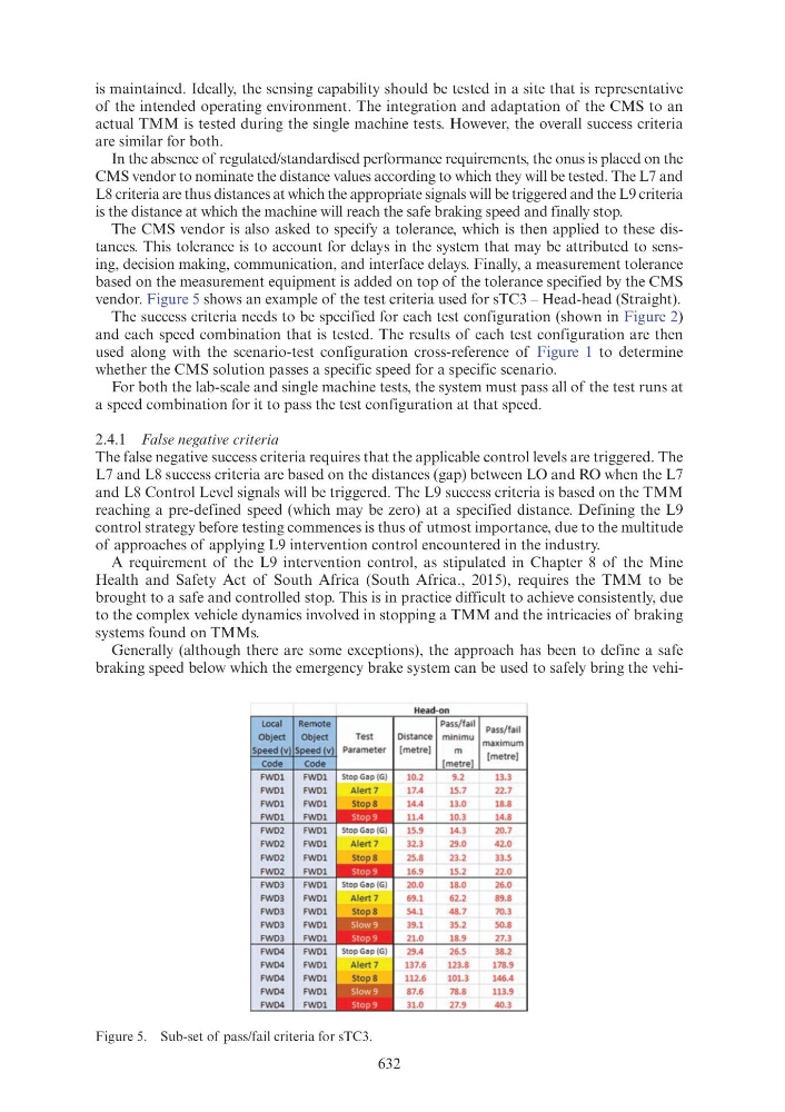
The CMS vendor is also asked to specify a tolerance, which is then applied to these distances. This tolerance is to account for delays in the system that may be attributed to sensing, decision making, communication, and interface delays. Finally, a measurement tolerance
based on the measurement equipment is added on top of the tolerance specified by the CMS
vendor. Figure 5 shows an example of the test criteria used for sTC3 – Head-head (Straight).
The success criteria needs to be specified for each test configuration (shown in Figure 2)
and each speed combination that is tested. The results of each test configuration are then
used along with the scenario-test configuration cross-reference of Figure 1 to determine
whether the CMS solution passes a specific speed for a specific scenario.
For both the lab-scale and single machine tests, the system must pass all of the test runs at
a speed combination for it to pass the test configuration at that speed.
2.4.1 False negative criteria
The false negative success criteria requires that the applicable control levels are triggered. The
L7 and L8 success criteria are based on the distances (gap) between LO and RO when the L7
and L8 Control Level signals will be triggered. The L9 success criteria is based on the TMM
reaching a pre-defined speed (which may be zero) at a specified distance. Defining the L9
control strategy before testing commences is thus of utmost importance, due to the multitude
of approaches of applying L9 intervention control encountered in the industry.
A requirement of the L9 intervention control, as stipulated in Chapter 8 of the Mine
Health and Safety Act of South Africa (South Africa., 2015), requires the TMM to be
brought to a safe and controlled stop. This is in practice difficult to achieve consistently, due
to the complex vehicle dynamics involved in stopping a TMM and the intricacies of braking
systems found on TMMs.
Generally (although there are some exceptions), the approach has been to define a safe
braking speed below which the emergency brake system can be used to safely bring the vehiFigure 5. Sub-set of pass/fail criteria for sTC3.
Head·on
Local
Remote
Pass/fail Pass/ fail
Obj ect
Obj ect
Test
Distance minimu maximum
[metre)
m
[metre]
10.2
9.2
13.3
FWD1
17.4
15.7
22.7
FWD1
14.4
13.0
18.8
FWD1
11.4
10.3
14.8
FWD2
15.9
14.3
20.7
FWD2
32.3
29.0
42.0
FWD2
25.8
23.2
33.5
FWD2
16.9
15.2
22.0
FWD3
20.0
18.0
26.0
FWD3
69.1
62.2
89.8
FWD3
54.1
48.7
70.3
FWD3
39.1
35.2
50.8
FWD3
21.0
18.9
27.3
FWD4
29.4
26.5
38.2
FWD4
137.6
123.8
178.9
FWD4
112.6
101.3
146.4
FWD4
87.6
78.8
113.9
FWD4
31.0
27.9
40.3