

587
of transport units and transport means have been reached. The FO-Network and the system
for material logistics were in use until mine was closed down in 2018.
2 SETTING UP A FIBER OTPIC NETWORK
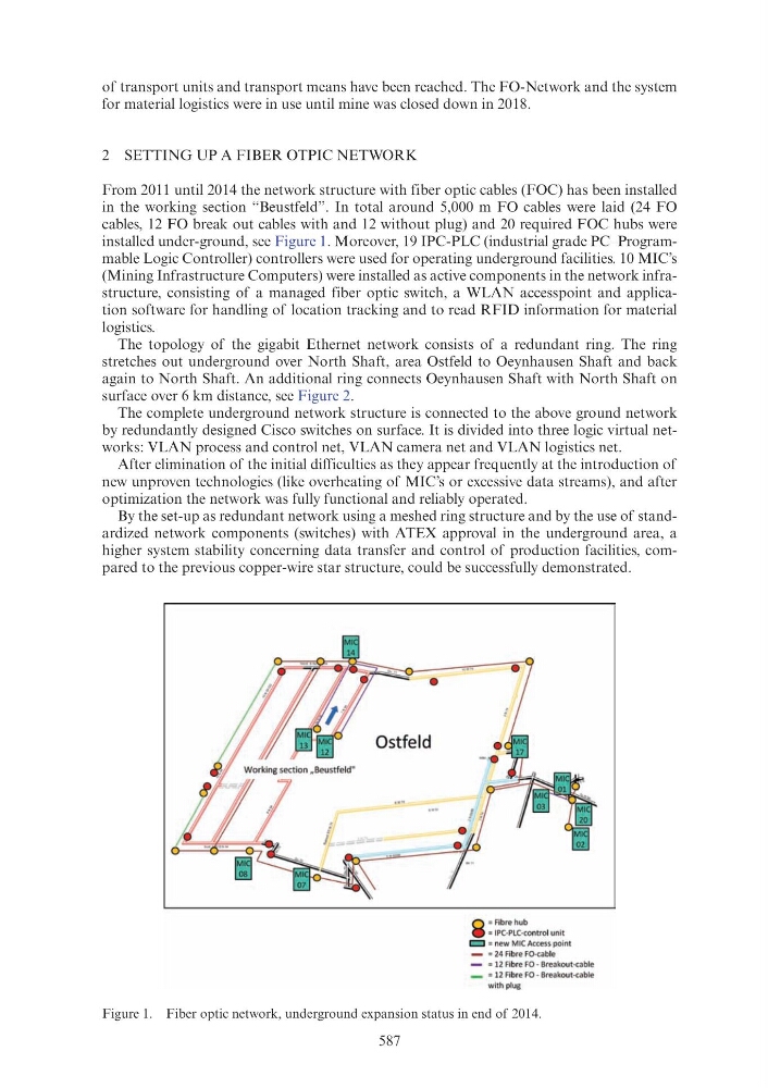
From 2011 until 2014 the network structure with fiber optic cables (FOC) has been installed
in the working section “Beustfeld”. In total around 5,000 m FO cables were laid (24 FO
cables, 12 FO break out cables with and 12 without plug) and 20 required FOC hubs were
installed under-ground, see Figure 1. Moreover, 19 IPC-PLC (industrial grade PC–Programmable Logic Controller) controllers were used for operating underground facilities. 10 MIC’s
(Mining Infrastructure Computers) were installed as active components in the network infrastructure, consisting of a managed fiber optic switch, a WLAN accesspoint and application software for handling of location tracking and to read RFID information for material
logistics.
The topology of the gigabit Ethernet network consists of a redundant ring. The ring
stretches out underground over North Shaft, area Ostfeld to Oeynhausen Shaft and back
again to North Shaft. An additional ring connects Oeynhausen Shaft with North Shaft on
surface over 6 km distance, see Figure 2.
The complete underground network structure is connected to the above ground network
by redundantly designed Cisco switches on surface. It is divided into three logic virtual networks: VLAN process and control net, VLAN camera net and VLAN logistics net.
After elimination of the initial difficulties as they appear frequently at the introduction of
new unproven technologies (like overheating of MIC’s or excessive data streams), and after
optimization the network was fully functional and reliably operated.
By the set-up as redundant network using a meshed ring structure and by the use of standardized network components (switches) with ATEX approval in the underground area, a
higher system stability concerning data transfer and control of production facilities, compared to the previous copper-wire star structure, could be successfully demonstrated.
Figure 1. Fiber optic network, underground expansion status in end of 2014.
•
Ostfeld
0 =Fibre hub
e = IPC-PLC-control unit
c::J = new M IC Access point
= 24 Fibre FO-cable
- = 12 Fibre FO- Breakout-cable
-
= 12 Fibre FO - Breakout-cable
w ith plug