

198
by 50 m by 1 m was used to fill the wireframe solids, complementing the 1 m composite sample
length from the drillholes. Boundaries between units are used to constrain grade estimation, to
prevent estimation across reductants of different character. Key geotechnical units, most notably
the pyritic siltstones, are coded into the model, and provide valuable input to mine planning.
In developing 3D models, a key objective was to retain the vertical and lateral variation evident to allow for optimisation of the mine design and schedule to maximise returns. Unlike
the earlier 2D models, no mining constraints were hard-coded into the models, ensuring flexibility to optimise cut-off grade.
The challenge in grade estimation is twofold:
– Retain the vertical bottom-loaded grade profile given the folding and thickness variations
within the mineralised horizon.
– Incorporate trends from stratigraphic modelling that will be used to control the search
orientation angles during estimation.
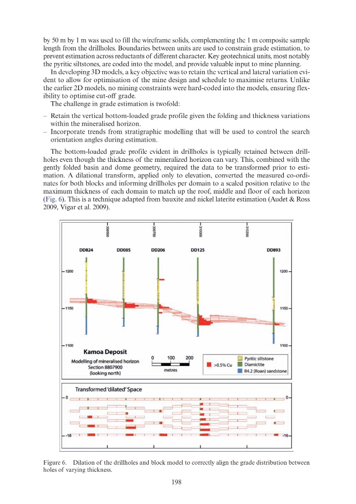
The bottom-loaded grade profile evident in drillholes is typically retained between drillholes even though the thickness of the mineralized horizon can vary. This, combined with the
gently folded basin and dome geometry, required the data to be transformed prior to estimation. A dilational transform, applied only to elevation, converted the measured co-ordinates for both blocks and informing drillholes per domain to a scaled position relative to the
maximum thickness of each domain to match up the roof, middle and floor of each horizon
(Fig. 6). This is a technique adapted from bauxite and nickel laterite estimation (Audet & Ross
2009, Vigar et al. 2009).
Figure 6. Dilation of the drillholes and block model to correctly align the grade distribution between
holes of varying thickness.
w
w
w
w
lli
~
g
~
8
0
8
g
DD824
DDOSS
DD206
DD125
DD893
J
1
1200
~
1200
-
~
~
1150
1150
::s ~
-~
~
~
1100
1100
Kamoa Deposit
Modelling of mineralised horizon
0
100
200
I· >0.5% Cu
EJ Pyritic siltstone
' I
I
I
.....
Section 8807900
-
• Diamictite
(loo king nort h)
metres
• R4.2 (Roan) sandstone
Transformed 'dilated' Space
0
0
c:::=I::::::::I:::::::::F=-r-----, c:::::::L:::::J
~ ~~~
=
==c::::=:::IJ
= =c:::::::o.-, = =
=
o:::::::::J
I
W
I
I
l_______L____j
L___j
L _ _
_ _ j
_ _ j
L___j
=
I
I
- ~ == _,--= = = -=
I
-
I
I I
..........
I
~~
-16----,
_,
I
:r:
_,
[
I
-
I
I
[
~
~
1 -----.----------:11 6
by 50 m by 1 m was used to fill the wireframe solids, complementing the 1 m composite sample
length from the drillholes. Boundaries between units are used to constrain grade estimation, to
prevent estimation across reductants of different character. Key geotechnical units, most notably
the pyritic siltstones, are coded into the model, and provide valuable input to mine planning.
In developing 3D models, a key objective was to retain the vertical and lateral variation evident to allow for optimisation of the mine design and schedule to maximise returns. Unlike
the earlier 2D models, no mining constraints were hard-coded into the models, ensuring flexibility to optimise cut-off grade.
The challenge in grade estimation is twofold:
– Retain the vertical bottom-loaded grade profile given the folding and thickness variations
within the mineralised horizon.
– Incorporate trends from stratigraphic modelling that will be used to control the search
orientation angles during estimation.
The bottom-loaded grade profile evident in drillholes is typically retained between drillholes even though the thickness of the mineralized horizon can vary. This, combined with the
gently folded basin and dome geometry, required the data to be transformed prior to estimation. A dilational transform, applied only to elevation, converted the measured co-ordinates for both blocks and informing drillholes per domain to a scaled position relative to the
maximum thickness of each domain to match up the roof, middle and floor of each horizon
(Fig. 6). This is a technique adapted from bauxite and nickel laterite estimation (Audet & Ross
2009, Vigar et al. 2009).
Figure 6. Dilation of the drillholes and block model to correctly align the grade distribution between
holes of varying thickness.
w
w
w
w
lli
~
g
~
8
0
8
g
DD824
DDOSS
DD206
DD125
DD893
J
1
1200
~
1200
-
~
~
1150
1150
::s ~
-~
~
~
1100
1100
Kamoa Deposit
Modelling of mineralised horizon
0
100
200
I· >0.5% Cu
EJ Pyritic siltstone
' I
I
I
.....
Section 8807900
-
• Diamictite
(loo king nort h)
metres
• R4.2 (Roan) sandstone
Transformed 'dilated' Space
0
0
c:::=I::::::::I:::::::::F=-r-----, c:::::::L:::::J
~ ~~~
=
==c::::=:::IJ
= =c:::::::o.-, = =
=
o:::::::::J
I
W
I
I
l_______L____j
L___j
L _ _
_ _ j
_ _ j
L___j
=
I
I
- ~ == _,--= = = -=
I
-
I
I I
..........
I
~~
-16----,
_,
I
:r:
_,
[
I
-
I
I
[
~
~
1 -----.----------:11 6