

Material balance
To crude unit
existing heat
exchange system
To new diesel
hydrotreater
surge drum
11
P303 A&B
326 gph
415°F
TIC
210°F
FICV
10
FICV
FIC
12
E-302
1420 gpm
9
13
To new
naphtha
hydrotreater
To sour
water stripper
P302 A&B
P301 A&B
LC
LCR
50 psig D301
90°F
TR
E-301
PR
PR
CV
From fuel
gas main
To flare
E-301 - Overhead condenser
Duty 157.373 mm BTU/h
Split range
D301 - Syn tower reflux drum
6’6” i/dx 20’20” T-T
and
4’0” i/d x 6’0” T-T
E-302 - Gas oil cooler
Duty 9.941 mm BTU/h
PR
CV
P-304 A&B
1024 gpm
LCV
LCV
LLV
5
600
75
135
89
152
125
120
27852
55703
17175
12881
7217
–
–
7361
9814
31830
15915
–
–
–
–
–
–
–
–
–
–
–
–
–
–
–
–
–
0.6070
0.6070
0.828
0.828
–
–
–
5000
140653
281300
118338
88755
58200
33200
18
–
–
–
–
–
18
6720
90
90
415
210
90
380
Steam
Steam
Naphtha
Naphtha
Gas oil
Pump
around
Soap
water
8
9
1 0
11
12
13
14
b
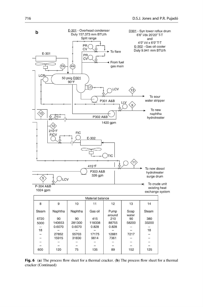
Fig. 6 (a) The process flow sheet for a thermal cracker. (b) The process flow sheet for a thermal
cracker (Continued)
716
D.S.J. Jones and P.R. Pujado ´