

Atm
Continuous Blowdown
BFW Makeup
Return
Lines
from
WHB
Boiler Circ
And Drag
Lines to
Steam Gens.
Intermit.
Blowdown
Stack
Steam Gen
Coils
Economizer
Coil
SMR Inlet
HDS
Super heat
Coil Option
ID Fan
SCR
Mod
Export Steam
Proc
Steam
Vent to Atm, Furnace, or Process Feed
Feed
Shift Condensate
To Degasifier/
Deaerator
Feed From Boiler Circ. Lines
Stripping
Steam
Makeup BFW
Degasifier/Deaerator
Waste Heat
Boiler
Intermittent
Blowdown
Drag Lines from Steam Drum
Steam Drum
BFW Storage
Return Lines to Steam Drum
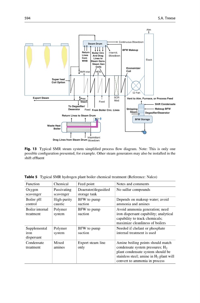
Fig. 13 Typical SMR steam system simplified process flow diagram. Note: This is only one
possible configuration presented, for example. Other steam generators may also be installed in the
shift effluent
Table 5 Typical SMR hydrogen plant boiler chemical treatment (Reference: Nalco)
Function
Chemical
Feed point
Notes and comments
Oxygen
scavenger
Passivating
scavenger
Deaerator/degasified
storage tank
No sulfur compounds
Boiler pH
control
High-purity
caustic
BFW to pump
suction
Depends on makeup water; avoid
ammonia and amines
Boiler internal
treatment
Polymer
system
BFW to pump
suction
Avoid ammonia generation; need
iron dispersant capability; analytical
capability to track chemicals;
maximize cleanliness of boilers
Supplemental
iron
dispersant
Polymer
system
BFW to pump
suction
Needed if chelant or phosphate
internal treatment is used
Condensate
treatment
Mixed
amines
Export steam line
only
Amine boiling points should match
condensate system pressures; H 2
plant condensate system should be
stainless steel; amine in H 2 plant will
convert to ammonia in process
594
S.A. Treese