

have very similar configurations and are flexible enough to be converted quite
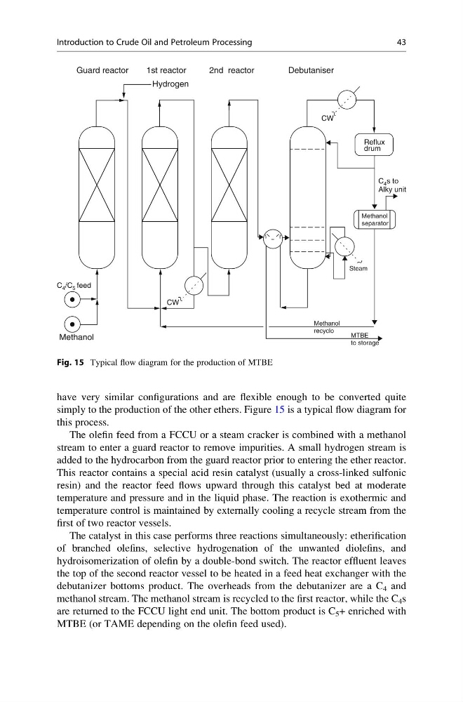
simply to the production of the other ethers. Figure 15 is a typical flow diagram for
this process.
The olefin feed from a FCCU or a steam cracker is combined with a methanol
stream to enter a guard reactor to remove impurities. A small hydrogen stream is
added to the hydrocarbon from the guard reactor prior to entering the ether reactor.
This reactor contains a special acid resin catalyst (usually a cross-linked sulfonic
resin) and the reactor feed flows upward through this catalyst bed at moderate
temperature and pressure and in the liquid phase. The reaction is exothermic and
temperature control is maintained by externally cooling a recycle stream from the
first of two reactor vessels.
The catalyst in this case performs three reactions simultaneously: etherification
of branched olefins, selective hydrogenation of the unwanted diolefins, and
hydroisomerization of olefin by a double-bond switch. The reactor effluent leaves
the top of the second reactor vessel to be heated in a feed heat exchanger with the
debutanizer bottoms product. The overheads from the debutanizer are a C 4 and
methanol stream. The methanol stream is recycled to the first reactor, while the C 4 s
are returned to the FCCU light end unit. The bottom product is C 5 + enriched with
MTBE (or TAME depending on the olefin feed used).
Guard reactor
1st reactor
Hydrogen
2nd reactor
Debutaniser
CW
Reflux
drum
C 4 s to
Alky unit
C 4 /C 5 feed
Methanol
Methanol
separator
Steam
Methanol
recyclo
MTBE
to storage
CW
Fig. 15 Typical flow diagram for the production of MTBE
Introduction to Crude Oil and Petroleum Processing
43
simply to the production of the other ethers. Figure 15 is a typical flow diagram for
this process.
The olefin feed from a FCCU or a steam cracker is combined with a methanol
stream to enter a guard reactor to remove impurities. A small hydrogen stream is
added to the hydrocarbon from the guard reactor prior to entering the ether reactor.
This reactor contains a special acid resin catalyst (usually a cross-linked sulfonic
resin) and the reactor feed flows upward through this catalyst bed at moderate
temperature and pressure and in the liquid phase. The reaction is exothermic and
temperature control is maintained by externally cooling a recycle stream from the
first of two reactor vessels.
The catalyst in this case performs three reactions simultaneously: etherification
of branched olefins, selective hydrogenation of the unwanted diolefins, and
hydroisomerization of olefin by a double-bond switch. The reactor effluent leaves
the top of the second reactor vessel to be heated in a feed heat exchanger with the
debutanizer bottoms product. The overheads from the debutanizer are a C 4 and
methanol stream. The methanol stream is recycled to the first reactor, while the C 4 s
are returned to the FCCU light end unit. The bottom product is C 5 + enriched with
MTBE (or TAME depending on the olefin feed used).
Guard reactor
1st reactor
Hydrogen
2nd reactor
Debutaniser
CW
Reflux
drum
C 4 s to
Alky unit
C 4 /C 5 feed
Methanol
Methanol
separator
Steam
Methanol
recyclo
MTBE
to storage
CW
Fig. 15 Typical flow diagram for the production of MTBE
Introduction to Crude Oil and Petroleum Processing
43