

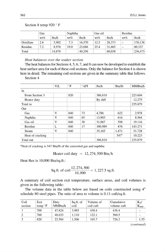
Section 8 temp 920
F
Gas
Naphtha
Gas oil
Residue
wt%
lbs/h
wt%
lbs/h
wt%
lbs/h
wt%
lbs/h
Distillate
2.6
5,902
7.3
16,570
12.5
28,373
–
176,136
Residue
7.2
8,976
19.0
23,686
25.4
31,665
–
60,337
Total
14,878
40,256
60,038
236,473
Heat balances over the soaker section
The heat balances for Sections 4, 5, 6, 7, and 8 can now be developed to establish the
heat surface area for each of these coil sections. Only the balance for Section 4 is shown
here in detail. The remaining coil sections are given in the summary table that follows.
Section 4
V/L
F
API
lbs/h
Btu/lb
MMBtu/h
In
From Section 3
820
386,810
223.604
Heater duty
By diff
12.275
Total in
235.879
Out
Gas
V
840
73
4,786
622
2.978
Naphtha
V
840
65
13,903
616
8.564
Gas oil
V
840
38
31,967
598
19.116
Residue
L
840
17
300,989
476
143.271
Steam
V
840
35,165
1,471
51.728
Heat of cracking
547
a
10.223
Total out
386,810
235.879
a
Heat of cracking is 547 Btu/lb of the converted gas and naphtha
Heater coil duty ¼ 12, 274, 500 Btu=h
Heat flux is 10,000 Btu/sq.ft.:
Sq:ft: of coil
12, 274, 500
10, 000
¼ 1, 227:5 sq:ft:
A summary of coil section exit temperature, surface areas, and coil volumes is
given in the following table:
The volume data in the table below are based on coils constructed using 4
00
schedule 80 steel pipes. The ratio of area to volume is 0.11 cuft/sq.ft.
Coil
section
Exit
temp
F
Duty
MMBtu/h
Sq.ft. of
coil
Volume of
coil cuft
Cumulative
volume cuft
K T /
K 800
1
700
47.824
3,985
438.4
438.4
–
2
760
48.633
1,110
122.1
560.5
–
3
820
22.584
1,506
165.7
726.2
1.55
(continued)
562
D.S.J. Jones
F
Gas
Naphtha
Gas oil
Residue
wt%
lbs/h
wt%
lbs/h
wt%
lbs/h
wt%
lbs/h
Distillate
2.6
5,902
7.3
16,570
12.5
28,373
–
176,136
Residue
7.2
8,976
19.0
23,686
25.4
31,665
–
60,337
Total
14,878
40,256
60,038
236,473
Heat balances over the soaker section
The heat balances for Sections 4, 5, 6, 7, and 8 can now be developed to establish the
heat surface area for each of these coil sections. Only the balance for Section 4 is shown
here in detail. The remaining coil sections are given in the summary table that follows.
Section 4
V/L
F
API
lbs/h
Btu/lb
MMBtu/h
In
From Section 3
820
386,810
223.604
Heater duty
By diff
12.275
Total in
235.879
Out
Gas
V
840
73
4,786
622
2.978
Naphtha
V
840
65
13,903
616
8.564
Gas oil
V
840
38
31,967
598
19.116
Residue
L
840
17
300,989
476
143.271
Steam
V
840
35,165
1,471
51.728
Heat of cracking
547
a
10.223
Total out
386,810
235.879
a
Heat of cracking is 547 Btu/lb of the converted gas and naphtha
Heater coil duty ¼ 12, 274, 500 Btu=h
Heat flux is 10,000 Btu/sq.ft.:
Sq:ft: of coil
12, 274, 500
10, 000
¼ 1, 227:5 sq:ft:
A summary of coil section exit temperature, surface areas, and coil volumes is
given in the following table:
The volume data in the table below are based on coils constructed using 4
00
schedule 80 steel pipes. The ratio of area to volume is 0.11 cuft/sq.ft.
Coil
section
Exit
temp
F
Duty
MMBtu/h
Sq.ft. of
coil
Volume of
coil cuft
Cumulative
volume cuft
K T /
K 800
1
700
47.824
3,985
438.4
438.4
–
2
760
48.633
1,110
122.1
560.5
–
3
820
22.584
1,506
165.7
726.2
1.55
(continued)
562
D.S.J. Jones