

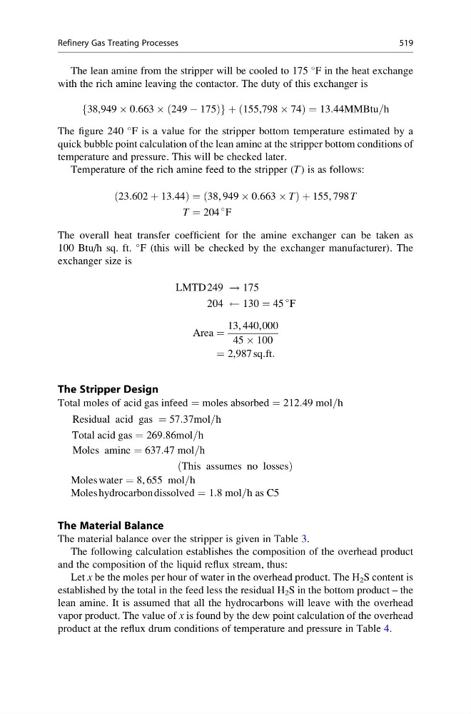
The lean amine from the stripper will be cooled to 175
F in the heat exchange
with the rich amine leaving the contactor. The duty of this exchanger is
38,949 Â 0:663 Â 249 À 175
ð
Þ
f
g þ 155,798 Â 74
ð
Þ¼13:44MMBtu=h
The figure 240
F is a value for the stripper bottom temperature estimated by a
quick bubble point calculation of the lean amine at the stripper bottom conditions of
temperature and pressure. This will be checked later.
Temperature of the rich amine feed to the stripper (T ) is as follows:
23:602 þ 13:44
ð
Þ ¼38, 949 Â 0:663 Â T
ð
Þ þ 155, 798 T
T ¼ 204
F
The overall heat transfer coefficient for the amine exchanger can be taken as
100 Btu/h sq. ft.
F (this will be checked by the exchanger manufacturer). The
exchanger size is
LMTD 249 ! 175
204
130 ¼ 45
F
Area ¼
13, 440,000
45 Â 100
¼ 2,987 sq:ft:
The Stripper Design
Total moles of acid gas infeed ¼ moles absorbed ¼ 212:49 mol=h
Residual acid gas ¼ 57:37mol=h
Total acid gas ¼ 269:86mol=h
Moles amine ¼ 637:47 mol=h
This assumes no losses
ð
Þ
Moles water ¼ 8, 655 mol=h
Moles hydrocarbon dissolved ¼ 1:8 mol=h as C5
The Material Balance
The material balance over the stripper is given in Table 3.
The following calculation establishes the composition of the overhead product
and the composition of the liquid reflux stream, thus:
Let x be the moles per hour of water in the overhead product. The H 2 S content is
established by the total in the feed less the residual H 2 S in the bottom product – the
lean amine. It is assumed that all the hydrocarbons will leave with the overhead
vapor product. The value of x is found by the dew point calculation of the overhead
product at the reflux drum conditions of temperature and pressure in Table 4.
Refinery Gas Treating Processes
519
F in the heat exchange
with the rich amine leaving the contactor. The duty of this exchanger is
38,949 Â 0:663 Â 249 À 175
ð
Þ
f
g þ 155,798 Â 74
ð
Þ¼13:44MMBtu=h
The figure 240
F is a value for the stripper bottom temperature estimated by a
quick bubble point calculation of the lean amine at the stripper bottom conditions of
temperature and pressure. This will be checked later.
Temperature of the rich amine feed to the stripper (T ) is as follows:
23:602 þ 13:44
ð
Þ ¼38, 949 Â 0:663 Â T
ð
Þ þ 155, 798 T
T ¼ 204
F
The overall heat transfer coefficient for the amine exchanger can be taken as
100 Btu/h sq. ft.
F (this will be checked by the exchanger manufacturer). The
exchanger size is
LMTD 249 ! 175
204
130 ¼ 45
F
Area ¼
13, 440,000
45 Â 100
¼ 2,987 sq:ft:
The Stripper Design
Total moles of acid gas infeed ¼ moles absorbed ¼ 212:49 mol=h
Residual acid gas ¼ 57:37mol=h
Total acid gas ¼ 269:86mol=h
Moles amine ¼ 637:47 mol=h
This assumes no losses
ð
Þ
Moles water ¼ 8, 655 mol=h
Moles hydrocarbon dissolved ¼ 1:8 mol=h as C5
The Material Balance
The material balance over the stripper is given in Table 3.
The following calculation establishes the composition of the overhead product
and the composition of the liquid reflux stream, thus:
Let x be the moles per hour of water in the overhead product. The H 2 S content is
established by the total in the feed less the residual H 2 S in the bottom product – the
lean amine. It is assumed that all the hydrocarbons will leave with the overhead
vapor product. The value of x is found by the dew point calculation of the overhead
product at the reflux drum conditions of temperature and pressure in Table 4.
Refinery Gas Treating Processes
519