

growth of hydrotreating, as of the beginning of 2001, there were more than 1,600
hydrotreaters operating in the world with a total capacity in excess of 39,000,000
B/D (4,800,000 MT/D).
Flow Schemes
Although the “hydrotreating process” has several different applications (e.g.,
hydrogenation, hydrodesulfurization, hydrodenitrogenation, hydrodemetallation,
etc.) and is used to process a variety of petroleum fractions from LPG all the way
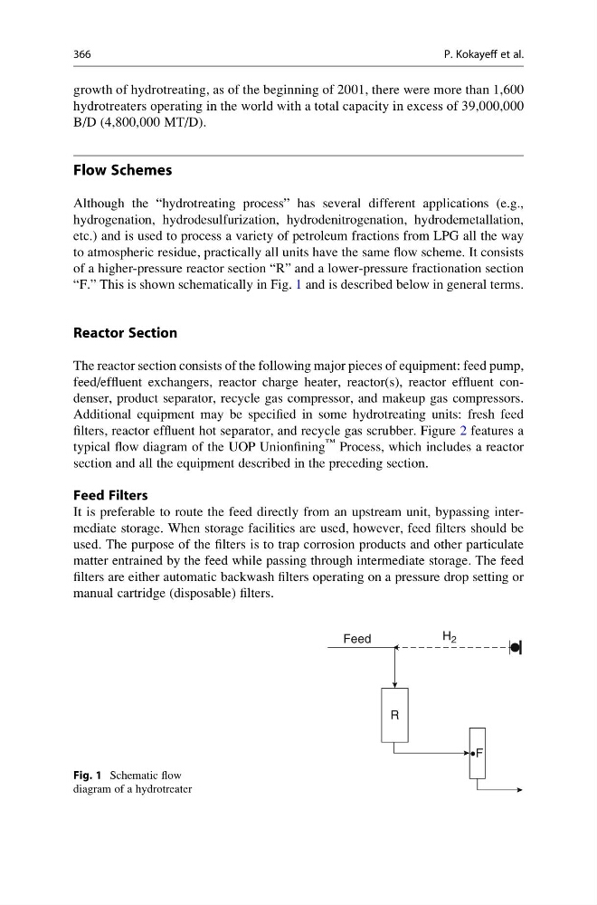
to atmospheric residue, practically all units have the same flow scheme. It consists
of a higher-pressure reactor section “R” and a lower-pressure fractionation section
“F.” This is shown schematically in Fig. 1 and is described below in general terms.
Reactor Section
The reactor section consists of the following major pieces of equipment: feed pump,
feed/effluent exchangers, reactor charge heater, reactor(s), reactor effluent condenser, product separator, recycle gas compressor, and makeup gas compressors.
Additional equipment may be specified in some hydrotreating units: fresh feed
filters, reactor effluent hot separator, and recycle gas scrubber. Figure 2 features a
typical flow diagram of the UOP Unionfining
™ Process, which includes a reactor
section and all the equipment described in the preceding section.
Feed Filters
It is preferable to route the feed directly from an upstream unit, bypassing intermediate storage. When storage facilities are used, however, feed filters should be
used. The purpose of the filters is to trap corrosion products and other particulate
matter entrained by the feed while passing through intermediate storage. The feed
filters are either automatic backwash filters operating on a pressure drop setting or
manual cartridge (disposable) filters.
H 2
Feed
R
•F
Fig. 1 Schematic flow
diagram of a hydrotreater
366
P. Kokayeff et al.
hydrotreaters operating in the world with a total capacity in excess of 39,000,000
B/D (4,800,000 MT/D).
Flow Schemes
Although the “hydrotreating process” has several different applications (e.g.,
hydrogenation, hydrodesulfurization, hydrodenitrogenation, hydrodemetallation,
etc.) and is used to process a variety of petroleum fractions from LPG all the way
to atmospheric residue, practically all units have the same flow scheme. It consists
of a higher-pressure reactor section “R” and a lower-pressure fractionation section
“F.” This is shown schematically in Fig. 1 and is described below in general terms.
Reactor Section
The reactor section consists of the following major pieces of equipment: feed pump,
feed/effluent exchangers, reactor charge heater, reactor(s), reactor effluent condenser, product separator, recycle gas compressor, and makeup gas compressors.
Additional equipment may be specified in some hydrotreating units: fresh feed
filters, reactor effluent hot separator, and recycle gas scrubber. Figure 2 features a
typical flow diagram of the UOP Unionfining
™ Process, which includes a reactor
section and all the equipment described in the preceding section.
Feed Filters
It is preferable to route the feed directly from an upstream unit, bypassing intermediate storage. When storage facilities are used, however, feed filters should be
used. The purpose of the filters is to trap corrosion products and other particulate
matter entrained by the feed while passing through intermediate storage. The feed
filters are either automatic backwash filters operating on a pressure drop setting or
manual cartridge (disposable) filters.
H 2
Feed
R
•F
Fig. 1 Schematic flow
diagram of a hydrotreater
366
P. Kokayeff et al.