

Many early FCC units had steam coils but these must be run at full load to
prevent a mechanical failure. All of these systems require a high water-to-steam
ratio to ensure vaporization does not occur in the regenerator coils or tubes, which
leads to hot spots and subsequent holes. Older heat removal systems were designed
with coils and trim coolers, but this concept has been rejected in modern resid
crackers.
The demand for residual fuels has steadily declined and it is unlikely that it will
ever return. Consequently, residual catalytic cracking is a high-growth area as
shown in Fig. 2.
Not much high-sulfur, heavy fuel oil will be sold in the future. Concern over acid
rain and the severe desulfurization required for transportation fuels will focus
100
80
60
40
20
0
Carbon Burned, % of Initial Carbon
1 st
Stage
Hydrogen Burned,
% of Initial
Hydrogen
2 nd
Stage
Either
Stage
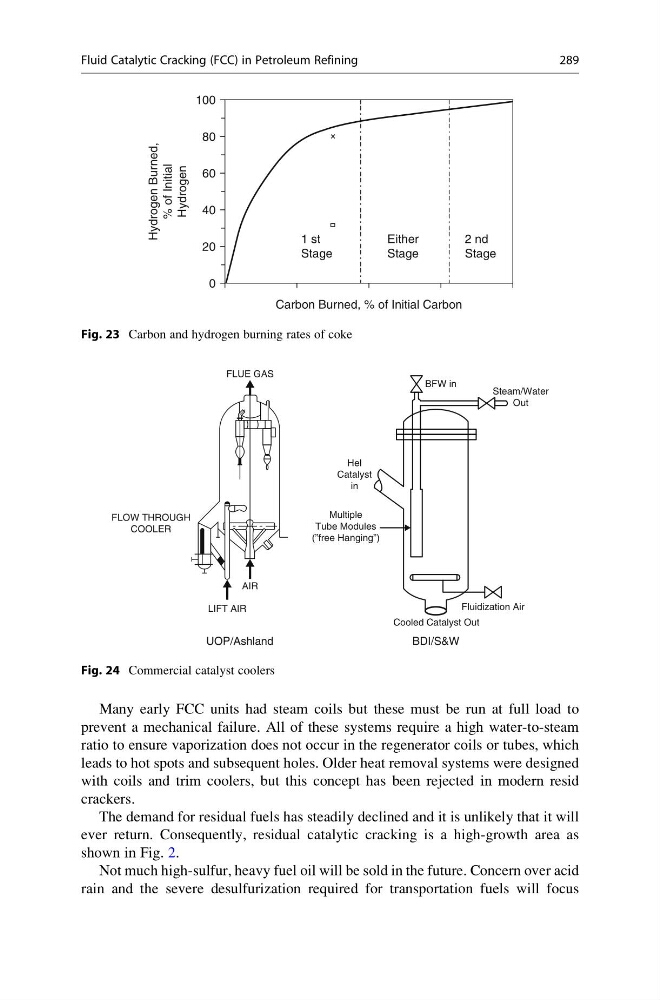
Fig. 23 Carbon and hydrogen burning rates of coke
BFW in
Steam/Water
Out
Fluidization Air
BDI/S&W
UOP/Ashland
LIFT AIR
AIR
FLUE GAS
FLOW THROUGH
COOLER
Hel
Catalyst
in
Multiple
Tube Modules
(”free Hanging”)
Cooled Catalyst Out
Fig. 24 Commercial catalyst coolers
Fluid Catalytic Cracking (FCC) in Petroleum Refining
289
prevent a mechanical failure. All of these systems require a high water-to-steam
ratio to ensure vaporization does not occur in the regenerator coils or tubes, which
leads to hot spots and subsequent holes. Older heat removal systems were designed
with coils and trim coolers, but this concept has been rejected in modern resid
crackers.
The demand for residual fuels has steadily declined and it is unlikely that it will
ever return. Consequently, residual catalytic cracking is a high-growth area as
shown in Fig. 2.
Not much high-sulfur, heavy fuel oil will be sold in the future. Concern over acid
rain and the severe desulfurization required for transportation fuels will focus
100
80
60
40
20
0
Carbon Burned, % of Initial Carbon
1 st
Stage
Hydrogen Burned,
% of Initial
Hydrogen
2 nd
Stage
Either
Stage
Fig. 23 Carbon and hydrogen burning rates of coke
BFW in
Steam/Water
Out
Fluidization Air
BDI/S&W
UOP/Ashland
LIFT AIR
AIR
FLUE GAS
FLOW THROUGH
COOLER
Hel
Catalyst
in
Multiple
Tube Modules
(”free Hanging”)
Cooled Catalyst Out
Fig. 24 Commercial catalyst coolers
Fluid Catalytic Cracking (FCC) in Petroleum Refining
289