

The reason for splitting the regeneration is to produce CO rather than CO 2 so that
external heat removal can be eliminated or reduced. Depending on the capacity of
the FCC unit, the heat removal by this technique can reach 100 million BTUs per
hour. Another benefit is that the hydrogen in the coke burns faster than the carbon as
shown in Fig. 23. This hydrogen is the chief source of moisture in the regeneration
process that has been shown to deactivate the catalyst. The carbon burn is typically
adjusted so that 45–75 % is accomplished in the first stage.
If even more heat removal is required, one or more catalyst coolers can be added
to the top regenerator. The two basic designs used are shown in Fig. 24.
Both are dense bed catalyst coolers. Dilute phase coolers were used in the past,
but frequent leaks made them too unreliable to use for commercial applications.
One of the designs features a shell and tube exchanger while the other has tube
clusters that have isolation valves. The latter is more expensive but allows isolation
of the leaking cluster without shutting down the catalyst cooler. If steam leaks into
the regenerator unabated, excessive catalyst deactivation occurs. The advantage of
a catalyst cooler is that its duty can be varied over virtually its entire heat load
range. This allows the refiner to adjust the coke make to the feedstock and desired
reaction severity.
Closed cyclone
system
Disengager
External plenum
Regenerator
Spent catalyst distribution
Air distributor
Dense phase catalyst cooler
Staged
stripper
Split feed
quench
Atomizing
feed injection
Lateral
Catalyst plug valve
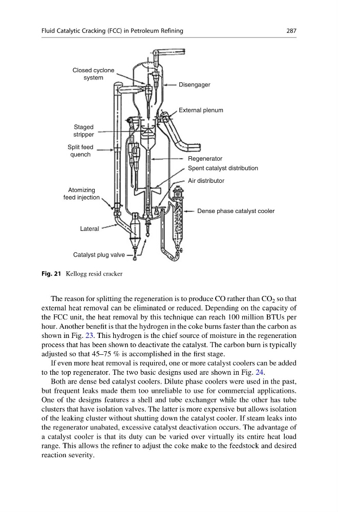
Fig. 21 Kellogg resid cracker
Fluid Catalytic Cracking (FCC) in Petroleum Refining
287
external heat removal can be eliminated or reduced. Depending on the capacity of
the FCC unit, the heat removal by this technique can reach 100 million BTUs per
hour. Another benefit is that the hydrogen in the coke burns faster than the carbon as
shown in Fig. 23. This hydrogen is the chief source of moisture in the regeneration
process that has been shown to deactivate the catalyst. The carbon burn is typically
adjusted so that 45–75 % is accomplished in the first stage.
If even more heat removal is required, one or more catalyst coolers can be added
to the top regenerator. The two basic designs used are shown in Fig. 24.
Both are dense bed catalyst coolers. Dilute phase coolers were used in the past,
but frequent leaks made them too unreliable to use for commercial applications.
One of the designs features a shell and tube exchanger while the other has tube
clusters that have isolation valves. The latter is more expensive but allows isolation
of the leaking cluster without shutting down the catalyst cooler. If steam leaks into
the regenerator unabated, excessive catalyst deactivation occurs. The advantage of
a catalyst cooler is that its duty can be varied over virtually its entire heat load
range. This allows the refiner to adjust the coke make to the feedstock and desired
reaction severity.
Closed cyclone
system
Disengager
External plenum
Regenerator
Spent catalyst distribution
Air distributor
Dense phase catalyst cooler
Staged
stripper
Split feed
quench
Atomizing
feed injection
Lateral
Catalyst plug valve
Fig. 21 Kellogg resid cracker
Fluid Catalytic Cracking (FCC) in Petroleum Refining
287