

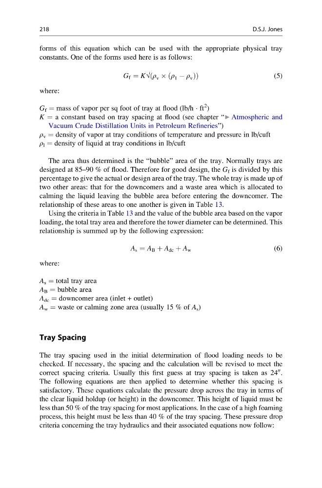
forms of this equation which can be used with the appropriate physical tray
constants. One of the forms used here is as follows:
G f ¼ K√ ρ v  ρ 1 À ρ v
ð
Þ
ð
Þ
(5)
where:
G f = mass of vapor per sq foot of tray at flood (lb/h Á ft
2 )
K = a constant based on tray spacing at flood (see chapter “▶ Atmospheric and
Vacuum Crude Distillation Units in Petroleum Refineries”)
ρ v = density of vapor at tray conditions of temperature and pressure in lb/cuft
ρ l = density of liquid at tray conditions in lb/cuft
The area thus determined is the “bubble” area of the tray. Normally trays are
designed at 85–90 % of flood. Therefore for good design, the G f is divided by this
percentage to give the actual or design area of the tray. The whole tray is made up of
two other areas: that for the downcomers and a waste area which is allocated to
calming the liquid leaving the bubble area before entering the downcomer. The
relationship of these areas to one another is given in Table 13.
Using the criteria in Table 13 and the value of the bubble area based on the vapor
loading, the total tray area and therefore the tower diameter can be determined. This
relationship is summed up by the following expression:
A s ¼ A B þ A dc þ A w
(6)
where:
A s = total tray area
A B = bubble area
A dc = downcomer area (inlet + outlet)
A w = waste or calming zone area (usually 15 % of A s )
Tray Spacing
The tray spacing used in the initial determination of flood loading needs to be
checked. If necessary, the spacing and the calculation will be revised to meet the
correct spacing criteria. Usually this first guess at tray spacing is taken as 24
00 .
The following equations are then applied to determine whether this spacing is
satisfactory. These equations calculate the pressure drop across the tray in terms of
the clear liquid holdup (or height) in the downcomer. This height of liquid must be
less than 50 % of the tray spacing for most applications. In the case of a high foaming
process, this height must be less than 40 % of the tray spacing. These pressure drop
criteria concerning the tray hydraulics and their associated equations now follow:
218
D.S.J. Jones
constants. One of the forms used here is as follows:
G f ¼ K√ ρ v  ρ 1 À ρ v
ð
Þ
ð
Þ
(5)
where:
G f = mass of vapor per sq foot of tray at flood (lb/h Á ft
2 )
K = a constant based on tray spacing at flood (see chapter “▶ Atmospheric and
Vacuum Crude Distillation Units in Petroleum Refineries”)
ρ v = density of vapor at tray conditions of temperature and pressure in lb/cuft
ρ l = density of liquid at tray conditions in lb/cuft
The area thus determined is the “bubble” area of the tray. Normally trays are
designed at 85–90 % of flood. Therefore for good design, the G f is divided by this
percentage to give the actual or design area of the tray. The whole tray is made up of
two other areas: that for the downcomers and a waste area which is allocated to
calming the liquid leaving the bubble area before entering the downcomer. The
relationship of these areas to one another is given in Table 13.
Using the criteria in Table 13 and the value of the bubble area based on the vapor
loading, the total tray area and therefore the tower diameter can be determined. This
relationship is summed up by the following expression:
A s ¼ A B þ A dc þ A w
(6)
where:
A s = total tray area
A B = bubble area
A dc = downcomer area (inlet + outlet)
A w = waste or calming zone area (usually 15 % of A s )
Tray Spacing
The tray spacing used in the initial determination of flood loading needs to be
checked. If necessary, the spacing and the calculation will be revised to meet the
correct spacing criteria. Usually this first guess at tray spacing is taken as 24
00 .
The following equations are then applied to determine whether this spacing is
satisfactory. These equations calculate the pressure drop across the tray in terms of
the clear liquid holdup (or height) in the downcomer. This height of liquid must be
less than 50 % of the tray spacing for most applications. In the case of a high foaming
process, this height must be less than 40 % of the tray spacing. These pressure drop
criteria concerning the tray hydraulics and their associated equations now follow:
218
D.S.J. Jones