

Step 4. Calculate the partial pressure of steam at the condenser pressure. This
pressure is the first/second stage intermediate pressure and is the suction pressure to the second ejector. It is read on the plant or it may be assumed. In the
calculation it is assumed to be 50 mmHg.
Step 5. From the partial pressure of steam, the condensing temperature in the
condenser is read from steam tables. Assume that 90 % steam is condensed in
this first condenser.
Step 6. (Optional) Calculate heat balance across the condenser and arrive at the
condenser duty.
Step 7. Repeat step 2 for “equivalent dry air load” to stage 2. Note: There will now
be steam present in this calculation.
Step 8. Repeat steps 3–5 for the second stage, making an assumption for the
condenser pressure or reading off the actual pressure if the unit is an installed
one. Assume also the amount of steam condensed in the second condenser – this
will be high around 98 %.
Step 9. Repeat steps 6 and 7 for the third stage condenser and ejector. This
condenser will be about 1 or 2 psi above atmospheric pressure.
Step 10. Summarize the above results into a process specification for a required
ejector set or, if already installed, compare the performance (e.g., calculated
steam consumed versus actual).
100
300 300
200 200
100 100
50 50
MOTIVE STEAM PRESSURE PAIG
MOTIVE STEAM PRESSURE PAIG
MOTIVE STEAM PRESSURE PAIG
MOTIVE STEAM PRESSURE PAIG
300 300
200 200
100 100
50 50
0.7 0.7
STEAM USAGE
STEAM USAGE
MULTIPLIER MULTIPLIER
STEAM USAGE
STEAM USAGE
MULTIPLIER MULTIPLIER
1.0 1.0
Mp Mp
Mp Mp
1.5 1.5
0.7 0.7 1.0 1.0 1.5 1.5 2.0 2.0
BASIC 100 PSIG
BASIC 100 PSIG
MOTIVE STEAM
MOTIVE STEAM
BASIC 150 PSIG
BASIC 150 PSIG
MOTIVE STEAM
MOTIVE STEAM
300
200
100
50
MOTIVE STEAM PRESSURE PSIG
MOTIVE STEAM PRESSURE PSIG
300
200
100
50
0.7
STEAM USAGE
MULTIPLIER
STEAM USAGE
MULTIPLIER
1.0
Mp
Mp
1.5
0.7 1.0 1.5 2.0
BASIS 100 PSIG
MOTIVE STEAM
BASIS 150 PSIG
MOTIVE STEAM
10
1
1
1
1
1
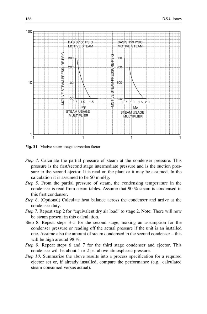
Fig. 31 Motive steam usage correction factor
186
D.S.J. Jones
pressure is the first/second stage intermediate pressure and is the suction pressure to the second ejector. It is read on the plant or it may be assumed. In the
calculation it is assumed to be 50 mmHg.
Step 5. From the partial pressure of steam, the condensing temperature in the
condenser is read from steam tables. Assume that 90 % steam is condensed in
this first condenser.
Step 6. (Optional) Calculate heat balance across the condenser and arrive at the
condenser duty.
Step 7. Repeat step 2 for “equivalent dry air load” to stage 2. Note: There will now
be steam present in this calculation.
Step 8. Repeat steps 3–5 for the second stage, making an assumption for the
condenser pressure or reading off the actual pressure if the unit is an installed
one. Assume also the amount of steam condensed in the second condenser – this
will be high around 98 %.
Step 9. Repeat steps 6 and 7 for the third stage condenser and ejector. This
condenser will be about 1 or 2 psi above atmospheric pressure.
Step 10. Summarize the above results into a process specification for a required
ejector set or, if already installed, compare the performance (e.g., calculated
steam consumed versus actual).
100
300 300
200 200
100 100
50 50
MOTIVE STEAM PRESSURE PAIG
MOTIVE STEAM PRESSURE PAIG
MOTIVE STEAM PRESSURE PAIG
MOTIVE STEAM PRESSURE PAIG
300 300
200 200
100 100
50 50
0.7 0.7
STEAM USAGE
STEAM USAGE
MULTIPLIER MULTIPLIER
STEAM USAGE
STEAM USAGE
MULTIPLIER MULTIPLIER
1.0 1.0
Mp Mp
Mp Mp
1.5 1.5
0.7 0.7 1.0 1.0 1.5 1.5 2.0 2.0
BASIC 100 PSIG
BASIC 100 PSIG
MOTIVE STEAM
MOTIVE STEAM
BASIC 150 PSIG
BASIC 150 PSIG
MOTIVE STEAM
MOTIVE STEAM
300
200
100
50
MOTIVE STEAM PRESSURE PSIG
MOTIVE STEAM PRESSURE PSIG
300
200
100
50
0.7
STEAM USAGE
MULTIPLIER
STEAM USAGE
MULTIPLIER
1.0
Mp
Mp
1.5
0.7 1.0 1.5 2.0
BASIS 100 PSIG
MOTIVE STEAM
BASIS 150 PSIG
MOTIVE STEAM
10
1
1
1
1
1
Fig. 31 Motive steam usage correction factor
186
D.S.J. Jones