

Number of trays = 12.
Factor is 12 Â 1.45 = 17.4.
50 % TBP difference between naphtha and Kero is 420–265 = 155
F.
ASTM Gap is 30
F which is within Spec.
Calculating the Remaining Tower Loadings
The tower loadings at the remaining critical sections of the tower are provided by
heat balances over the envelopes given in the heat balance diagram (Fig. 23). These
critical sections are:
• Below bottom pumparound drawoff (envelope 1)
• Below top pumparound drawoff (envelope 2)
• Below Kero drawoff (envelope 3)
Strip out & Steam to Main Tower
Un stripped
HGO From
Main Tower
Four Stripping Trays
Steam
Stripped
HGO Product
Heat In:
HGO Tray Draw off (Un Stripped HGO)
Steam
Heat Out:HGO Product
Strip Out
Steam.
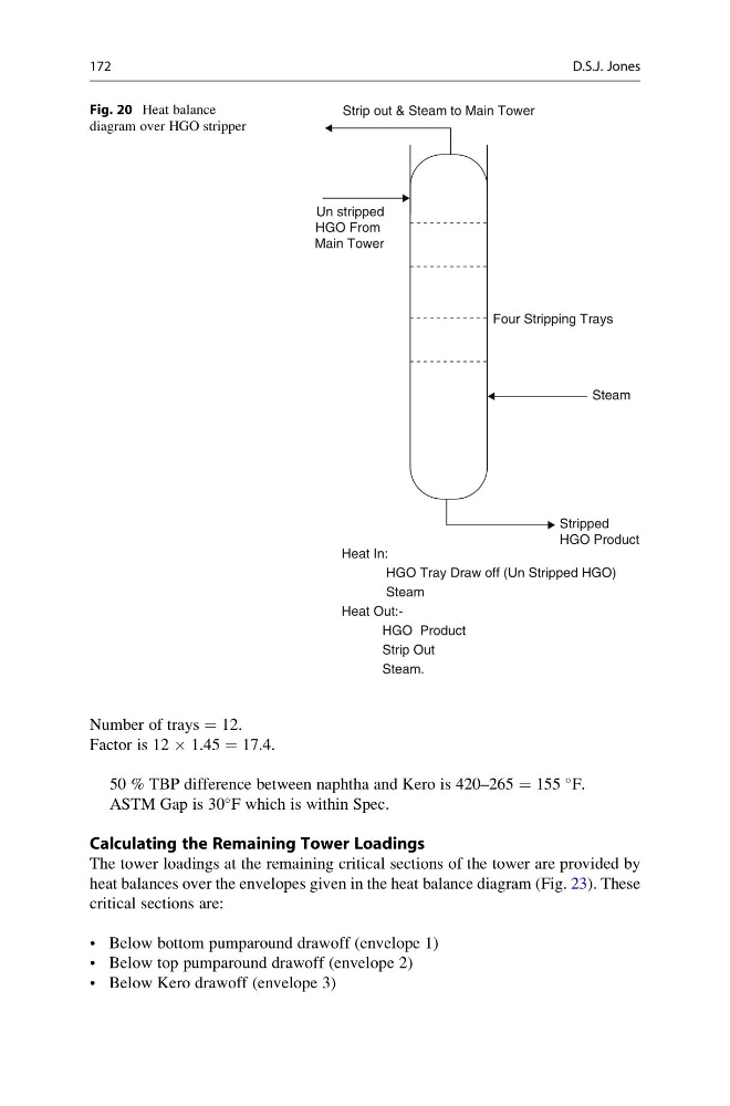
Fig. 20 Heat balance
diagram over HGO stripper
172
D.S.J. Jones
Factor is 12 Â 1.45 = 17.4.
50 % TBP difference between naphtha and Kero is 420–265 = 155
F.
ASTM Gap is 30
F which is within Spec.
Calculating the Remaining Tower Loadings
The tower loadings at the remaining critical sections of the tower are provided by
heat balances over the envelopes given in the heat balance diagram (Fig. 23). These
critical sections are:
• Below bottom pumparound drawoff (envelope 1)
• Below top pumparound drawoff (envelope 2)
• Below Kero drawoff (envelope 3)
Strip out & Steam to Main Tower
Un stripped
HGO From
Main Tower
Four Stripping Trays
Steam
Stripped
HGO Product
Heat In:
HGO Tray Draw off (Un Stripped HGO)
Steam
Heat Out:HGO Product
Strip Out
Steam.
Fig. 20 Heat balance
diagram over HGO stripper
172
D.S.J. Jones