

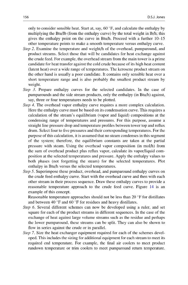
only to consider sensible heat. Start at, say, 60
F, and calculate the enthalpy by
multiplying the Btu/lb (from the enthalpy curve) by the total weight in lb/h; this
gives the enthalpy point on the curve in Btu/h. Proceed with a further 10–15
other temperature points to make a smooth temperature versus enthalpy curve.
Step 2. Examine the temperature and weight/h of the overhead, pumparound, and
product streams. Select those that will be candidates for heat exchange against
the crude feed. For example, the overhead stream from the main tower is a prime
candidate for heat transfer against the cold crude because of its high heat content
(latent heat) over a wide range of temperatures. The kerosene product stream on
the other hand is usually a poor candidate. It contains only sensible heat over a
short temperature range and is also probably the smallest product stream by
weight.
Step 3. Prepare enthalpy curves for the selected candidates. In the case of
pumparounds and the side stream products, only the enthalpy (in Btu/h) against,
say, three or four temperatures needs to be plotted.
Step 4. The overhead vapor enthalpy curve requires a more complex calculation.
Here the enthalpy curve must be based on its condensation curve. This requires a
calculation of the stream’s equilibrium (vapor and liquid) compositions at the
condensing range of temperatures and pressures. For this purpose, assume a
straight line pressure drop and temperature profiles between tower top and reflux
drum. Select four to five pressures and their corresponding temperatures. For the
purpose of this calculation, it is assumed that no steam condenses in this segment
of the system; therefore, the equilibrium constants are taken at the partial
pressure with steam. Using the overhead vapor composition (in mol/h) from
the sum of overhead product plus reflux vapor, calculate its vapor/liquid composition at the selected temperatures and pressure. Apply the enthalpy values to
both phases (not forgetting the steam) for the selected temperatures. Plot
enthalpy in Btu/h versus the selected temperatures.
Step 5. Superimpose these product, overhead, and pumparound enthalpy curves on
the crude feed enthalpy curve. Start with the overhead curve and then with each
other stream in their process sequence. Draw these enthalpy curves to provide a
reasonable temperature approach to the crude feed curve. Figure 14 is an
example of this concept.
Reasonable temperature approaches should not be less than 20
F for distillates
and between 40
F and 60
F for residues and heavy distillates.
Step 6. Several different schemes can now be developed using a ruler, and set
square for each of the product streams in different sequences. In the case of the
exchange of heat against large volume streams such as the residue and perhaps
the lower pumparound, these streams can be split. They can also be shown to
flow in series against the crude or in parallel.
Step 7. Size the heat exchanger equipment required for each of the schemes developed. This includes the sizing for additional equipment for each stream to meet its
required end temperature. For example, the final air coolers to meet product
rundown temperature or trim coolers to meet pumparound return temperature.
156
D.S.J. Jones
F, and calculate the enthalpy by
multiplying the Btu/lb (from the enthalpy curve) by the total weight in lb/h; this
gives the enthalpy point on the curve in Btu/h. Proceed with a further 10–15
other temperature points to make a smooth temperature versus enthalpy curve.
Step 2. Examine the temperature and weight/h of the overhead, pumparound, and
product streams. Select those that will be candidates for heat exchange against
the crude feed. For example, the overhead stream from the main tower is a prime
candidate for heat transfer against the cold crude because of its high heat content
(latent heat) over a wide range of temperatures. The kerosene product stream on
the other hand is usually a poor candidate. It contains only sensible heat over a
short temperature range and is also probably the smallest product stream by
weight.
Step 3. Prepare enthalpy curves for the selected candidates. In the case of
pumparounds and the side stream products, only the enthalpy (in Btu/h) against,
say, three or four temperatures needs to be plotted.
Step 4. The overhead vapor enthalpy curve requires a more complex calculation.
Here the enthalpy curve must be based on its condensation curve. This requires a
calculation of the stream’s equilibrium (vapor and liquid) compositions at the
condensing range of temperatures and pressures. For this purpose, assume a
straight line pressure drop and temperature profiles between tower top and reflux
drum. Select four to five pressures and their corresponding temperatures. For the
purpose of this calculation, it is assumed that no steam condenses in this segment
of the system; therefore, the equilibrium constants are taken at the partial
pressure with steam. Using the overhead vapor composition (in mol/h) from
the sum of overhead product plus reflux vapor, calculate its vapor/liquid composition at the selected temperatures and pressure. Apply the enthalpy values to
both phases (not forgetting the steam) for the selected temperatures. Plot
enthalpy in Btu/h versus the selected temperatures.
Step 5. Superimpose these product, overhead, and pumparound enthalpy curves on
the crude feed enthalpy curve. Start with the overhead curve and then with each
other stream in their process sequence. Draw these enthalpy curves to provide a
reasonable temperature approach to the crude feed curve. Figure 14 is an
example of this concept.
Reasonable temperature approaches should not be less than 20
F for distillates
and between 40
F and 60
F for residues and heavy distillates.
Step 6. Several different schemes can now be developed using a ruler, and set
square for each of the product streams in different sequences. In the case of the
exchange of heat against large volume streams such as the residue and perhaps
the lower pumparound, these streams can be split. They can also be shown to
flow in series against the crude or in parallel.
Step 7. Size the heat exchanger equipment required for each of the schemes developed. This includes the sizing for additional equipment for each stream to meet its
required end temperature. For example, the final air coolers to meet product
rundown temperature or trim coolers to meet pumparound return temperature.
156
D.S.J. Jones