

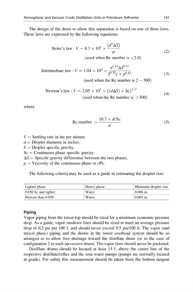
The design of the drum to allow this separation is based on one of three laws.
These laws are expressed by the following equations:
Stoke’s law : V ¼ 8:3 Â 10
5
Â
d
2
ΔS
À
Á
μ
used when Re number is <2:0
ð
Þ
(2)
Intermediate law : V ¼ 1:04 Â 10
4
Â
d
1:14
ΔS
0:71
S
0:29 c  μ 0:43
used when the Re number is 2 À 500
ð
Þ
(3)
Newton’s law : V ¼ 2:05 Â 10
3
 dΔS
ð
ÞÄSc
f
g
1=2
used when the Re number is >500
ð
Þ
(4)
where
Re number ¼
10:7 Â dcSc
μ
(5)
V = Settling rate in ins per minute.
d = Droplet diameter in inches.
S = Droplet specific gravity.
Sc = Continuous phase specific gravity.
ΔS = Specific gravity differential between the two phases.
μ = Viscosity of the continuous phase in cPs.
The following criteria may be used as a guide to estimating the droplet size:
Lighter phase
Heavy phase
Minimum droplet size
0.850 Sc and lighter
Water
0.008 in.
Heavier than 0.850
Water
0.005 in.
Piping
Vapor piping from the tower top should be sized for a minimum economic pressure
drop. As a guide, vapor rundown lines should be sized to meet an average pressure
drop of 0.2 psi per 100 f. and should never exceed 0.5 psi/100 ft. The vapor (and
mixed phase) piping and the drums in the tower overhead system should be so
arranged as to allow free drainage toward the distillate drum (or in the case of
configuration 2 to each successive drum). The vapor lines should never be pocketed.
Distillate drums should be located at least 15 f. above the center line of the
respective distillate/reflux and the sour water pumps (pumps are normally located
at grade). For safety this measurement should be taken from the bottom tangent
Atmospheric and Vacuum Crude Distillation Units in Petroleum Refineries
141
These laws are expressed by the following equations:
Stoke’s law : V ¼ 8:3 Â 10
5
Â
d
2
ΔS
À
Á
μ
used when Re number is <2:0
ð
Þ
(2)
Intermediate law : V ¼ 1:04 Â 10
4
Â
d
1:14
ΔS
0:71
S
0:29 c  μ 0:43
used when the Re number is 2 À 500
ð
Þ
(3)
Newton’s law : V ¼ 2:05 Â 10
3
 dΔS
ð
ÞÄSc
f
g
1=2
used when the Re number is >500
ð
Þ
(4)
where
Re number ¼
10:7 Â dcSc
μ
(5)
V = Settling rate in ins per minute.
d = Droplet diameter in inches.
S = Droplet specific gravity.
Sc = Continuous phase specific gravity.
ΔS = Specific gravity differential between the two phases.
μ = Viscosity of the continuous phase in cPs.
The following criteria may be used as a guide to estimating the droplet size:
Lighter phase
Heavy phase
Minimum droplet size
0.850 Sc and lighter
Water
0.008 in.
Heavier than 0.850
Water
0.005 in.
Piping
Vapor piping from the tower top should be sized for a minimum economic pressure
drop. As a guide, vapor rundown lines should be sized to meet an average pressure
drop of 0.2 psi per 100 f. and should never exceed 0.5 psi/100 ft. The vapor (and
mixed phase) piping and the drums in the tower overhead system should be so
arranged as to allow free drainage toward the distillate drum (or in the case of
configuration 2 to each successive drum). The vapor lines should never be pocketed.
Distillate drums should be located at least 15 f. above the center line of the
respective distillate/reflux and the sour water pumps (pumps are normally located
at grade). For safety this measurement should be taken from the bottom tangent
Atmospheric and Vacuum Crude Distillation Units in Petroleum Refineries
141