

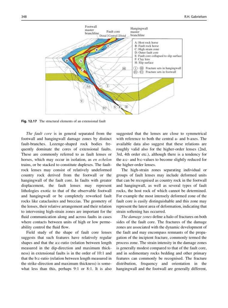
The fault core is in general separated from the
footwall and hangingwall damage zones by distinct
fault-branches. Lozenge-shaped rock bodies frequently dominate the cores of extensional faults.
These are commonly referred to as fault lenses or
horses, which may occur in isolation, as en echelon
trains, or be stacked to constitute duplexes. The faultrock lenses may consist of relatively undeformed
country rock derived from the footwall or the
hangingwall of the fault core. In faults with greater
displacement, the fault lenses may represent
lithologies exotic to that of the observable footwall
and hangingwall or be completely reworked fault
rocks like cataclasites and breccias. The geometry of
the lenses, their relative arrangement and their relation
to intervening high-strain zones are important for the
fluid communication along and across faults in cases
where contacts between units of high or low permeability control the fluid flow.
Field study of the shape of fault core lenses
suggests that such features have relatively regular
shapes and that the a:c-ratio (relation between length
measured in the dip-direction and maximum thickness) in extensional faults is in the order of 10:1 and
that the b:c-ratio (relation between length measured in
the strike-direction and maximum thickness) is somewhat less than this, perhaps 9:1 or 8:1. It is also
suggested that the lenses are close to symmetrical
with reference to both the central a- and b-axes. The
available data also suggest that these relations are
roughly valid also for the higher-order lenses (2nd,
3rd, 4th order etc.), although there is a tendency for
the a:c- and b:c-values to become slightly reduced for
the higher-order lenses.
The high-strain zones separating individual or
groups of fault lenses may include deformed units
that can be recognised as country rock in the footwall
and hangingwall, as well as several types of fault
rocks, the host rock of which cannot be determined.
For example the most intensely deformed zone of the
fault core is easily distinguishable and this zone may
represent the latest area of deformation, indicating that
strain softening has occurred.
The damage zones define a halo of fractures on both
sides of the fault core. The fractures of the damage
zones are associated with the dynamic development of
the fault and may encompass remnants of the propagation of the incipient fracture, commonly termed the
process zone. The strain intensity in the damage zones
is generally modest compared to that of the fault core,
and in sedimentary rocks bedding and other primary
features can commonly be recognised. The fracture
distribution, frequency and orientation in the
hangingwall and the footwall are generally different,
Footwall
master
branchline
Fault core
Hangingwall
master
branchline
A: Host rock horse
B: Fault rock horse
C: High strain zone
D: Outer fault core
E: Fault core collapsed to slip surface
F: Clay lens
H: Slip surface
Fracture sets in hangingwall
Fracture sets in footwall
I
I
III
-
-
III
VI
VI
IV
V
V E
II
C
D
A
B
F
IV
Distal Central Distal
Fig. 12.17 The structural elements of an extensional fault
348
R.H. Gabrielsen
footwall and hangingwall damage zones by distinct
fault-branches. Lozenge-shaped rock bodies frequently dominate the cores of extensional faults.
These are commonly referred to as fault lenses or
horses, which may occur in isolation, as en echelon
trains, or be stacked to constitute duplexes. The faultrock lenses may consist of relatively undeformed
country rock derived from the footwall or the
hangingwall of the fault core. In faults with greater
displacement, the fault lenses may represent
lithologies exotic to that of the observable footwall
and hangingwall or be completely reworked fault
rocks like cataclasites and breccias. The geometry of
the lenses, their relative arrangement and their relation
to intervening high-strain zones are important for the
fluid communication along and across faults in cases
where contacts between units of high or low permeability control the fluid flow.
Field study of the shape of fault core lenses
suggests that such features have relatively regular
shapes and that the a:c-ratio (relation between length
measured in the dip-direction and maximum thickness) in extensional faults is in the order of 10:1 and
that the b:c-ratio (relation between length measured in
the strike-direction and maximum thickness) is somewhat less than this, perhaps 9:1 or 8:1. It is also
suggested that the lenses are close to symmetrical
with reference to both the central a- and b-axes. The
available data also suggest that these relations are
roughly valid also for the higher-order lenses (2nd,
3rd, 4th order etc.), although there is a tendency for
the a:c- and b:c-values to become slightly reduced for
the higher-order lenses.
The high-strain zones separating individual or
groups of fault lenses may include deformed units
that can be recognised as country rock in the footwall
and hangingwall, as well as several types of fault
rocks, the host rock of which cannot be determined.
For example the most intensely deformed zone of the
fault core is easily distinguishable and this zone may
represent the latest area of deformation, indicating that
strain softening has occurred.
The damage zones define a halo of fractures on both
sides of the fault core. The fractures of the damage
zones are associated with the dynamic development of
the fault and may encompass remnants of the propagation of the incipient fracture, commonly termed the
process zone. The strain intensity in the damage zones
is generally modest compared to that of the fault core,
and in sedimentary rocks bedding and other primary
features can commonly be recognised. The fracture
distribution, frequency and orientation in the
hangingwall and the footwall are generally different,
Footwall
master
branchline
Fault core
Hangingwall
master
branchline
A: Host rock horse
B: Fault rock horse
C: High strain zone
D: Outer fault core
E: Fault core collapsed to slip surface
F: Clay lens
H: Slip surface
Fracture sets in hangingwall
Fracture sets in footwall
I
I
III
-
-
III
VI
VI
IV
V
V E
II
C
D
A
B
F
IV
Distal Central Distal
Fig. 12.17 The structural elements of an extensional fault
348
R.H. Gabrielsen