

include stratigraphic trap elements (Fig. 12.11, trap
type 5). The trap depends on the sealing of the fault
zone. This trap type is initiated before accommodation
structures are activated, and may therefore be
characterised by wide extension towards the basin
centre. The trap size and complexity depend upon
sediment influx relative to basin floor subsidence rate
and the stability (potential for reactivation) of the
master fault.
In these syn-rift traps the width of the belt of reservoir sand/conglomerate out from the master fault zone
is directly related to the subsidence rate and the size of
the crestal area being drained. Abundant sediment
supply and moderate subsidence rates will cause larger
radius fans to develop, whereas high subsidence rates
cause all clastic sediment to be trapped in much
narrower belts in the immediate vicinity of the fault.
This trap type is well known from the late Jurassic
interval in the North Sea, where the most prominent
examples are the Brae Field and the Magnus Field.
Because the coarse-sediment gravity-flow sands and
conglomerates are restricted to narrow fault-parallel
belts, they commonly have problematic low continuity
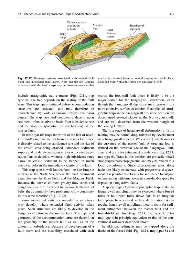
in this same direction (Fig. 12.12).
Fans associated with accommodation structures
may develop where extended fault activity takes
place. Such structures are likely to develop in the
hangingwall close to the master fault. The type and
geometry of the accommodation structure depend on
the geometry of the master fault as well as on the
amount of subsidence. Because of development of a
fault scarp and the instability associated with such
scarps, the foot-wall fault block is likely to be the
major source for the hangingwall catchment, even
though the hangingwall dip slope may represent the
more extensive surface of erosion. Examples of stratigraphic traps in the hangingwall dip-slope position are
documented several places in the Norwegian shelf,
and are well described from the western margin of
the Viking Graben.
The first stage of hangingwall deformation in listric
faulting may be normal drag, followed by development
of a hangingwall anticline (“roll-over”) which mirrors
the curvature of the master fault. A structural low is
defined on the proximal side of the hangingwall anticline, and opens for entrapment of sediments (Fig. 12.11,
trap type 6). Traps in this position are primarily mixed
stratigraphic/palaeotopographic and may be related to a
local unconformity. Since displacement rates along
faults are likely to increase with progressive displacement, it is possible also locally for subsidence to outpace
sedimentation with time, to create considerable space for
deposition along active faults.
A special type of palaeotopographic trap related to
hangingwall anticlines may be expected where forced
folds or fault-bend folds above flats in an irregular
fault plane have caused surface deformation. As in
regular hangingwall anticlines, there is room for sediment entrapment between the master fault and the
forced-fold anticline (Fig. 12.11, trap type 9). This
trap type is in principle equivalent to that of the conventional roll-over described above.
In addition, sediments may be trapped along the
flanks of the forced fold (Fig. 12.11, trap types 8a and
Drainage system
of footwall
uplands
Relay
ramp
Marginal
high
Axial
drainage
system
Hangingwall
dip slope
Fig. 12.12 Drainage systems associated with rotated fault
block and associated fault scarps. Note that the fan systems
associated with the fault scarps may be discontinuous and that
sand is also derived from the rotated hanging wall fault block.
Modified from Nøttvedt, Gabrielsen and Steel (1995)
12 The Structure and Hydrocarbon Traps of Sedimentary Basins
335
type 5). The trap depends on the sealing of the fault
zone. This trap type is initiated before accommodation
structures are activated, and may therefore be
characterised by wide extension towards the basin
centre. The trap size and complexity depend upon
sediment influx relative to basin floor subsidence rate
and the stability (potential for reactivation) of the
master fault.
In these syn-rift traps the width of the belt of reservoir sand/conglomerate out from the master fault zone
is directly related to the subsidence rate and the size of
the crestal area being drained. Abundant sediment
supply and moderate subsidence rates will cause larger
radius fans to develop, whereas high subsidence rates
cause all clastic sediment to be trapped in much
narrower belts in the immediate vicinity of the fault.
This trap type is well known from the late Jurassic
interval in the North Sea, where the most prominent
examples are the Brae Field and the Magnus Field.
Because the coarse-sediment gravity-flow sands and
conglomerates are restricted to narrow fault-parallel
belts, they commonly have problematic low continuity
in this same direction (Fig. 12.12).
Fans associated with accommodation structures
may develop where extended fault activity takes
place. Such structures are likely to develop in the
hangingwall close to the master fault. The type and
geometry of the accommodation structure depend on
the geometry of the master fault as well as on the
amount of subsidence. Because of development of a
fault scarp and the instability associated with such
scarps, the foot-wall fault block is likely to be the
major source for the hangingwall catchment, even
though the hangingwall dip slope may represent the
more extensive surface of erosion. Examples of stratigraphic traps in the hangingwall dip-slope position are
documented several places in the Norwegian shelf,
and are well described from the western margin of
the Viking Graben.
The first stage of hangingwall deformation in listric
faulting may be normal drag, followed by development
of a hangingwall anticline (“roll-over”) which mirrors
the curvature of the master fault. A structural low is
defined on the proximal side of the hangingwall anticline, and opens for entrapment of sediments (Fig. 12.11,
trap type 6). Traps in this position are primarily mixed
stratigraphic/palaeotopographic and may be related to a
local unconformity. Since displacement rates along
faults are likely to increase with progressive displacement, it is possible also locally for subsidence to outpace
sedimentation with time, to create considerable space for
deposition along active faults.
A special type of palaeotopographic trap related to
hangingwall anticlines may be expected where forced
folds or fault-bend folds above flats in an irregular
fault plane have caused surface deformation. As in
regular hangingwall anticlines, there is room for sediment entrapment between the master fault and the
forced-fold anticline (Fig. 12.11, trap type 9). This
trap type is in principle equivalent to that of the conventional roll-over described above.
In addition, sediments may be trapped along the
flanks of the forced fold (Fig. 12.11, trap types 8a and
Drainage system
of footwall
uplands
Relay
ramp
Marginal
high
Axial
drainage
system
Hangingwall
dip slope
Fig. 12.12 Drainage systems associated with rotated fault
block and associated fault scarps. Note that the fan systems
associated with the fault scarps may be discontinuous and that
sand is also derived from the rotated hanging wall fault block.
Modified from Nøttvedt, Gabrielsen and Steel (1995)
12 The Structure and Hydrocarbon Traps of Sedimentary Basins
335