

where p 0 is a reference stress to make the ratio inside
the parenthesis non-dimensional (often p 0 is set equal
to 0.1 MPa in the published literature), and “m” and
“a” are non-dimensional coefficients depending on the
type of sediment and its geological history. To fit the
different experimental curves, the exponent “a” is
found to lie between 0 and 1. For a normally
consolidated clay sediment a ¼ 1 and this fits quite
well, and the effective stress σ
0 v gives an M t
value which is directly proportional to σ v . For
overconsolidated clay sediments (weak claystones)
an a-value of 0 gives a fair approximation, and that
corresponds to an M t which is constant as given by the
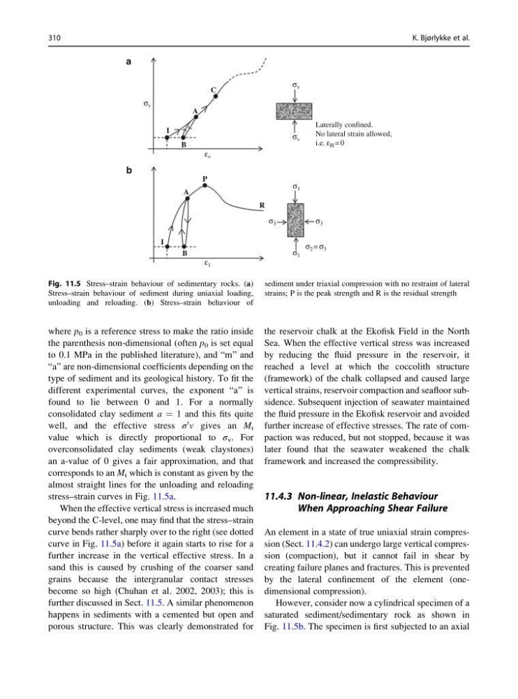
almost straight lines for the unloading and reloading
stress–strain curves in Fig. 11.5a.
When the effective vertical stress is increased much
beyond the C-level, one may find that the stress–strain
curve bends rather sharply over to the right (see dotted
curve in Fig. 11.5a) before it again starts to rise for a
further increase in the vertical effective stress. In a
sand this is caused by crushing of the coarser sand
grains because the intergranular contact stresses
become so high (Chuhan et al. 2002, 2003); this is
further discussed in Sect. 11.5. A similar phenomenon
happens in sediments with a cemented but open and
porous structure. This was clearly demonstrated for
the reservoir chalk at the Ekofisk Field in the North
Sea. When the effective vertical stress was increased
by reducing the fluid pressure in the reservoir, it
reached a level at which the coccolith structure
(framework) of the chalk collapsed and caused large
vertical strains, reservoir compaction and seafloor subsidence. Subsequent injection of seawater maintained
the fluid pressure in the Ekofisk reservoir and avoided
further increase of effective stresses. The rate of compaction was reduced, but not stopped, because it was
later found that the seawater weakened the chalk
framework and increased the compressibility.
11.4.3 Non-linear, Inelastic Behaviour
When Approaching Shear Failure
An element in a state of true uniaxial strain compression (Sect. 11.4.2) can undergo large vertical compression (compaction), but it cannot fail in shear by
creating failure planes and fractures. This is prevented
by the lateral confinement of the element (onedimensional compression).
However, consider now a cylindrical specimen of a
saturated sediment/sedimentary rock as shown in
Fig. 11.5b. The specimen is first subjected to an axial
a
b
A
Laterally confined.
No lateral strain allowed,
i.e. ε H = 0
C
R
P
A
I
B
B
I
σ v
σ v
σ 1
σ 3
σ 3
σ 1
σ 2 = σ 3
σ v
ε v
ε 1
Fig. 11.5 Stress–strain behaviour of sedimentary rocks. (a)
Stress–strain behaviour of sediment during uniaxial loading,
unloading and reloading. (b) Stress–strain behaviour of
sediment under triaxial compression with no restraint of lateral
strains; P is the peak strength and R is the residual strength
310
K. Bjørlykke et al.
the parenthesis non-dimensional (often p 0 is set equal
to 0.1 MPa in the published literature), and “m” and
“a” are non-dimensional coefficients depending on the
type of sediment and its geological history. To fit the
different experimental curves, the exponent “a” is
found to lie between 0 and 1. For a normally
consolidated clay sediment a ¼ 1 and this fits quite
well, and the effective stress σ
0 v gives an M t
value which is directly proportional to σ v . For
overconsolidated clay sediments (weak claystones)
an a-value of 0 gives a fair approximation, and that
corresponds to an M t which is constant as given by the
almost straight lines for the unloading and reloading
stress–strain curves in Fig. 11.5a.
When the effective vertical stress is increased much
beyond the C-level, one may find that the stress–strain
curve bends rather sharply over to the right (see dotted
curve in Fig. 11.5a) before it again starts to rise for a
further increase in the vertical effective stress. In a
sand this is caused by crushing of the coarser sand
grains because the intergranular contact stresses
become so high (Chuhan et al. 2002, 2003); this is
further discussed in Sect. 11.5. A similar phenomenon
happens in sediments with a cemented but open and
porous structure. This was clearly demonstrated for
the reservoir chalk at the Ekofisk Field in the North
Sea. When the effective vertical stress was increased
by reducing the fluid pressure in the reservoir, it
reached a level at which the coccolith structure
(framework) of the chalk collapsed and caused large
vertical strains, reservoir compaction and seafloor subsidence. Subsequent injection of seawater maintained
the fluid pressure in the Ekofisk reservoir and avoided
further increase of effective stresses. The rate of compaction was reduced, but not stopped, because it was
later found that the seawater weakened the chalk
framework and increased the compressibility.
11.4.3 Non-linear, Inelastic Behaviour
When Approaching Shear Failure
An element in a state of true uniaxial strain compression (Sect. 11.4.2) can undergo large vertical compression (compaction), but it cannot fail in shear by
creating failure planes and fractures. This is prevented
by the lateral confinement of the element (onedimensional compression).
However, consider now a cylindrical specimen of a
saturated sediment/sedimentary rock as shown in
Fig. 11.5b. The specimen is first subjected to an axial
a
b
A
Laterally confined.
No lateral strain allowed,
i.e. ε H = 0
C
R
P
A
I
B
B
I
σ v
σ v
σ 1
σ 3
σ 3
σ 1
σ 2 = σ 3
σ v
ε v
ε 1
Fig. 11.5 Stress–strain behaviour of sedimentary rocks. (a)
Stress–strain behaviour of sediment during uniaxial loading,
unloading and reloading. (b) Stress–strain behaviour of
sediment under triaxial compression with no restraint of lateral
strains; P is the peak strength and R is the residual strength
310
K. Bjørlykke et al.