

96
maps uncertain contacts and structures are indi�
cated by dashed or dotted lines, and geological units
that cannot be mapped separately may be shown
unsubdivided. The same illustrative devices should
be used on outcrop profiles. It is important to remember, however, that the classification of bounding surfaces and lithosomes, according to the
systems described in this chapter, is an interpretive
process. The classification is firmly grounded on
observable attributes, such as the shape of the
bounding surfaces, and the facies associations of the
deposits immediately above and below, but a degree
of interpretation is commonly required to produce a
fully annotated profile.
It is recommended that the major bounding surfaces in each profile, of fifth-order rank and higher,
be lettered in sequence from the base of the outcrop
upwards, using capital letters. The architectural elements bounded by these surfaces are then numbered
in the same order, using Arabic numerals. This system provides a basic reference framework for describing the profile.
Each prof!le should be lettered separately, using a
local lettering and numbering sequence, unless profiles can be correlated laterally. If specific bounding
surfaces can be traced between outcrops, it may be
useful to use the same lettering and numbering sequence throughout, but it must be remembered that
fluvial deposits tend to be characterized by rapid
lateral changes in facies and architecture, and it cannot be assumed that surfaces and elements can be
correlated across unexposed areas, unless there is a
DED UC TIVE
LEVELS I
2
'
FIELD EVIDENCE
LOCAL
FL UVIAL REGIME
Methods of Architectu ra l-Element Analysis
considerable amount of internal evidence to suggest
such correlations.
Additional details can be added to the annotation, where this is deemed useful. Bounding surfaces
of third- and fourth-order rank may be designated
by primes or some other form of superscript added
to the surface lettering. Architectural elements so
subdivided may be designated by the letters A, B, C,
etc. added to the element number. The element code
may be added after this number, where a reliable
interpretation can be arrived at. A complete profile
annotation may then look something like this:
4-SB
D
(5th order)
3C-DA
C'
(4th order)
3B-DA
CJ
(4th order)
3A-LA
c
(5th order)
2-LA
B
(5th order)
1-SB
A
(5th order)
Some sandstones sheets are built by a complex
process of cutting and filling> so that only fragments
of the ban and minor channel fills are preserved in
the final deposit, many of which may not extend
completely across the outcrop. Numbering of the
elements and subelements must then be carried out
REASONI NG
4
5
CLIMATIC VARIABLES
Precipitalion
(Me
Evapor
Paleochannel
CONDITIONS
-
Morphology
aod
Velocity
Sedimentotogy
Sediment Transport
Gr odienl
Channel Pottem
�
Hydraulic Geometr
{width, depth,
hydraulic radius)
/ SpaHal Vadatiaol
�I MEN
Oroinoge Densit
S
Ruggedness
eaiiThiokMJ � GEOLOGIC VA RIABLES
I
l
FEED BA C.K
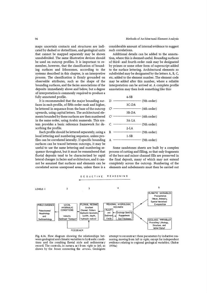
Fig. 4.14. Flow diagram showing the relationships between geologi cal and climatic va ri ables to hydrauli c conditions and the resulting fluvial style and sedimentary
re co rd. The controls, in nature> act from right -to left , as
shown by the boxes co nnecting the arrows. Geologists
Prevailing lilhology,
Structure, and
Initial Relief
attempt to re construct these pa ramete rs by inductive reasoning, moving from left to right, except fo r independent
evidence relating to regional geological va ri ables. (B aker
1978a)
maps uncertain contacts and structures are indi�
cated by dashed or dotted lines, and geological units
that cannot be mapped separately may be shown
unsubdivided. The same illustrative devices should
be used on outcrop profiles. It is important to remember, however, that the classification of bounding surfaces and lithosomes, according to the
systems described in this chapter, is an interpretive
process. The classification is firmly grounded on
observable attributes, such as the shape of the
bounding surfaces, and the facies associations of the
deposits immediately above and below, but a degree
of interpretation is commonly required to produce a
fully annotated profile.
It is recommended that the major bounding surfaces in each profile, of fifth-order rank and higher,
be lettered in sequence from the base of the outcrop
upwards, using capital letters. The architectural elements bounded by these surfaces are then numbered
in the same order, using Arabic numerals. This system provides a basic reference framework for describing the profile.
Each prof!le should be lettered separately, using a
local lettering and numbering sequence, unless profiles can be correlated laterally. If specific bounding
surfaces can be traced between outcrops, it may be
useful to use the same lettering and numbering sequence throughout, but it must be remembered that
fluvial deposits tend to be characterized by rapid
lateral changes in facies and architecture, and it cannot be assumed that surfaces and elements can be
correlated across unexposed areas, unless there is a
DED UC TIVE
LEVELS I
2
'
FIELD EVIDENCE
LOCAL
FL UVIAL REGIME
Methods of Architectu ra l-Element Analysis
considerable amount of internal evidence to suggest
such correlations.
Additional details can be added to the annotation, where this is deemed useful. Bounding surfaces
of third- and fourth-order rank may be designated
by primes or some other form of superscript added
to the surface lettering. Architectural elements so
subdivided may be designated by the letters A, B, C,
etc. added to the element number. The element code
may be added after this number, where a reliable
interpretation can be arrived at. A complete profile
annotation may then look something like this:
4-SB
D
(5th order)
3C-DA
C'
(4th order)
3B-DA
CJ
(4th order)
3A-LA
c
(5th order)
2-LA
B
(5th order)
1-SB
A
(5th order)
Some sandstones sheets are built by a complex
process of cutting and filling> so that only fragments
of the ban and minor channel fills are preserved in
the final deposit, many of which may not extend
completely across the outcrop. Numbering of the
elements and subelements must then be carried out
REASONI NG
4
5
CLIMATIC VARIABLES
Precipitalion
(Me
Evapor
Paleochannel
CONDITIONS
-
Morphology
aod
Velocity
Sedimentotogy
Sediment Transport
Gr odienl
Channel Pottem
�
Hydraulic Geometr
{width, depth,
hydraulic radius)
/ SpaHal Vadatiaol
�I MEN
Oroinoge Densit
S
Ruggedness
eaiiThiokMJ � GEOLOGIC VA RIABLES
I
l
FEED BA C.K
Fig. 4.14. Flow diagram showing the relationships between geologi cal and climatic va ri ables to hydrauli c conditions and the resulting fluvial style and sedimentary
re co rd. The controls, in nature> act from right -to left , as
shown by the boxes co nnecting the arrows. Geologists
Prevailing lilhology,
Structure, and
Initial Relief
attempt to re construct these pa ramete rs by inductive reasoning, moving from left to right, except fo r independent
evidence relating to regional geological va ri ables. (B aker
1978a)