

100
5 Development of a Simulation-based Methodology …
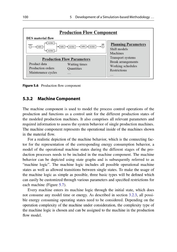
Figure 5.6 Production flow component
5.3.2 Machine Component
The machine component is used to model the process control operations of the
production and functions as a control unit for the different production states of
the modeled production machines. It also comprises all relevant parameters and
required information to assess the system behavior of single production machines.
The machine component represents the operational inside of the machines shown
in the material flow.
For a realistic depiction of the machine behavior, which is the connecting factor for the representation of the corresponding energy consumption behavior, a
model of the operational machine states during the different stages of the production processes needs to be included in the machine component. The machine
behavior can be depicted using state graphs and is subsequently referred to as
“machine logic”. The machine logic includes all possible operational machine
states as well as allowed transitions between single states. To make the usage of
the machine logic as simple as possible, three basic types will be defined which
can easily be customized through various parameters and specified restrictions for
each machine (Figure 5.7).
Every machine enters its machine logic through the initial state, which does
not consume any model time or energy. As described in section 3.2.3, all possible energy consuming operating states need to be considered. Depending on the
operation complexity of the machine under consideration, the complexity type of
the machine logic is chosen and can be assigned to the machine in the production
flow model.
5 Development of a Simulation-based Methodology …
Figure 5.6 Production flow component
5.3.2 Machine Component
The machine component is used to model the process control operations of the
production and functions as a control unit for the different production states of
the modeled production machines. It also comprises all relevant parameters and
required information to assess the system behavior of single production machines.
The machine component represents the operational inside of the machines shown
in the material flow.
For a realistic depiction of the machine behavior, which is the connecting factor for the representation of the corresponding energy consumption behavior, a
model of the operational machine states during the different stages of the production processes needs to be included in the machine component. The machine
behavior can be depicted using state graphs and is subsequently referred to as
“machine logic”. The machine logic includes all possible operational machine
states as well as allowed transitions between single states. To make the usage of
the machine logic as simple as possible, three basic types will be defined which
can easily be customized through various parameters and specified restrictions for
each machine (Figure 5.7).
Every machine enters its machine logic through the initial state, which does
not consume any model time or energy. As described in section 3.2.3, all possible energy consuming operating states need to be considered. Depending on the
operation complexity of the machine under consideration, the complexity type of
the machine logic is chosen and can be assigned to the machine in the production
flow model.